400 Series Standard Options:
Optional Main Beam Lengths (B-XXX):
Main Beams may be ordered in any length from 26″ to 104″ between Trunnion Interface Mounts and 56″ to 104″ on HD fixtures. Above 104″ requires special beams. Below 26″ can be dangerous due to tip over. “XXX” = length in inches between Trunnion Interface Mounts. (1″ increments)
While the two End Frames can be adjusted toward each other to accommodate smaller length parts, excessively long beams with a small part will leave the Main Beams extending from each End Frame enough to be inconvenient. It therefore is desirable to order this Main Beam close to the size of the actual part-to-be-handled.
Optional Telescopic Main Beams (TB):
Telescopic Main Beams adjust from 62″ to 110″ between Trunnion Interface Mounts (and 56″ to 104″ on HD fixtures). They will do this without extending beyond the End frames. They can be adjusted down to 26″ between Interface mounts by letting them extend beyond the End frames.
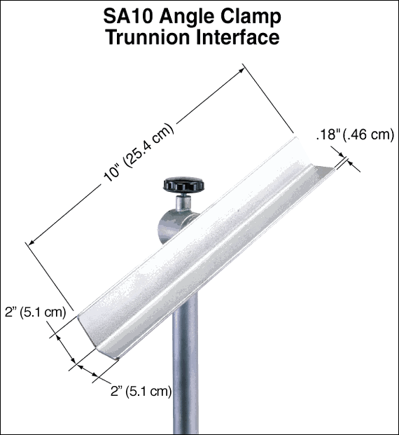
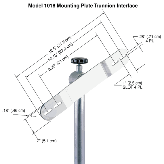
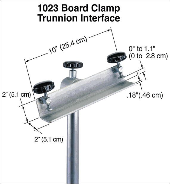
Optional Trunnion Interface/Mount/Clamp:
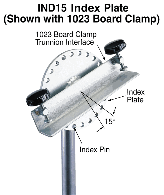
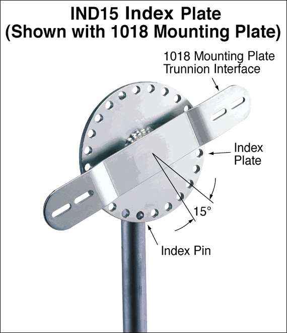
Optional Index Plate (IND15):
Indexed @ 15° increments to prevent trunnion rotation with a lock pin. An Index plate can be supplied with either of the mounting interfaces, shown below or the SA10 angle interface. NOTE: Addition of an optional index plate decreases the vertical adjustment from 10″ to 8″.
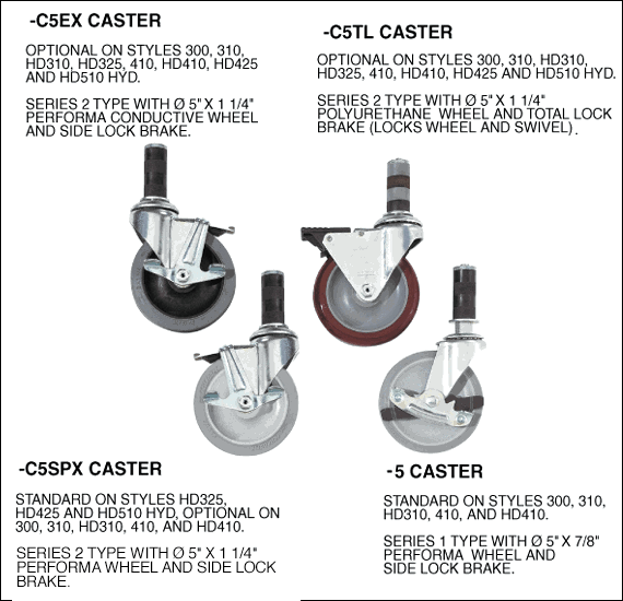
Optional Casters:
1. Standard Series 1 swivel caster (-5) – Metal sidelock brake and 5″ diameter x 7/8″ wide Performa wheel
2. Optional heavy duty Series 2 swivel caster with Side-lock brake (C5SPX)
3. Optional heavy duty Series 2 swivel caster with total lock brake (C5TL)
4. Optional heavy duty Series 2 swivel caster with conductive wheel (C5EX)
Optional Gearbox:
The larger 715 gearbox with 50:1 ratio and 6″ diameter crank is available in place of the standard 713 gearbox.
Optional Fixture Finishes for use in Clean Room (C):
The fixture is supplied with most surfaces electroless nickel plated, the gearbox case is painted with white epoxy and miscellaneous hardware is made of stainless steel.
Optional Ground Lug and Drag Chain (E):
For use in electrostatically protected areas (EPA’s). Proper electrostatic discharge (ESD) grounding of the fixture must be part of the overall EPA design. (see Technical section discussion on ESD
Gearbox Mounted Push Bar (P1):
The push bar is mounted underneath the gearbox and improves ergonomics of intra-facility transport of the Flotron. Having a handle for leverage can make a huge difference to ease transportation. The gearbox mounted push bar can be retrofitted on existing Flotron Rotation Fixtures.
Optional Lubricants:
Krytox GPL 207 (L1) – The trunnions are lubricated with Krytox GPL 207. Note that this lubricant comes standard on “C” (Clean Room) finish and does not need to be specified.
Braycote 601EF (L2) – The trunnions are lubricated with Braycote 601EF.
Standard Proof Load Test (PLT):
Proof Load Test Procedure:
Dead weight load (no rotation), visual inspection.
- Static proof load test.
- Vertical load only.
- 150% vertical load, 100% torque.
- Hold load for 5 minutes minimum.
- Customer may witness test.
- Paint and plating covers all welds.
- Visually inspect for cracks, deformation, etc.
A deliverable proof load test report will be provided. The report will include a summary of the test procedure, actual measured weight of load applied, visual inspection results, and images of the test being performed.
Special Options:
If a standard holding fixture does not meet your requirements, contact Flotron about custom modifications. Often, minor modifications to a standard unit are all you will need and can be done cost effectively.
As Flotron is constantly improving products and methods of manufacturing, we reserve the right to modify and/or change design or specifications without notice. Please contact Flotron for verification of critical dimensions and specifications.
For 400 Series – Creating a Model Number pdf click here
For clarification of terms or phrases, please see the Holding Fixtures Definitions page.
