SFP-700 Series Options:
Optional Fixture Finishes (C):
(Blank): Standard finishes. Flotron blue powder coated end frames, gearbox painted Flotron blue, nickel plated steel or black oxide fasteners, misc. hardware, and components. Standard lubricants.
Clean room option (C): This option includes no zinc components like the standard finish option but with the addition of electro-less nickel-plating on the interior of the end frame slide tubes and vertical support tubes. The end frames are powder coated gloss sky white and the gearbox is painted gloss white epoxy. Krytox GPL 207 lubricant is applied to the caster swivel bearings, trunnion bearings, and the leveling jack screws (covered in housings) unless the (L2) Lubricant option is selected.
Optional Ground Lug and Drag Chain (E):
For use in electrostatically protected areas (EPA’s). Each end frame has a 5/16-24 brass ground lug with nut for attaching a grounding strap. Additionally, each end frame has stainless-steel drag chains to ground to a conductive floor (See technical section discussion on ESD for more information on grounding).
Optional Lubricants:
Krytox GPL 207 (L1) – The leveling jack screws (if applicable) and caster swivel bearings are lubricated with Krytox GPL 207. Note that this lubricant comes standard on “C” (Clean Room) finish and does not need to be specified.
Braycote 601EF (L2) – The leveling jacks (if applicable) and caster swivel bearings are lubricated with Braycote 601EF.
Optional Electromechanical Lift (EML):
Electrically powered actuators raise and lower the trunnion height with a push button control. The unit can be powered via a standard 3 prong power plug (NEMA 5-15R) or an optional battery power (see BAT option below). Power requirements are 100-240VAC, 50-60HZ, 600W. The raise and lower speed is fixed at 11.5 inces/minute and is not adjustable. The up/down buttons can be jogged to raise and lower at a slower speed if desired. Duty cycle is 10% max (2 minutes continuous use followed by 18 minutes not in use). The unit will retain position when turned off so no homing function is necessary during normal use.
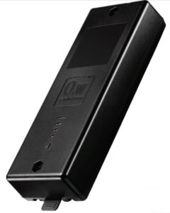
Optional Battery Power for Electro-Mechanical Lift Option (BAT):
A battery can be added to power the electro-mechanical lift fixtures. This reduces the need for a power cable to be plugged in during use. This may be useful in areas where cables pose a trip hazard, get in the way, or where electrical outlets are far away. The control box will periodically need to be plugged in to re-charge the battery. The operator can expect to get approximately 7-9 (depending on configuration and payload weight) full stroke up/down cycles under max load before charging is necessary. Under lighter loads or partial stroke, the battery can go longer before charging is necessary. There are light bars on the unit that indicate remaining capacity.
Optional Forklift Tubes(F1):
Forklift tubes are bolted to the bottom of the end frames and span the length of the fixture. They are designed with a stiffener I-beam welded to the top of the forklift tube to increase rigidity. For an unloaded fixture, it is critical that the fork extends at least two feet past the fixture CG. When lifting the fixture with the payload integrated, the forks should extend through the entire length of the forklift tubes. If you are unsure of how long the lifting forks need to be for your application, please contact Flotron. The forklift tube option can be retrofitted on existing Flotron Rotation Fixtures.
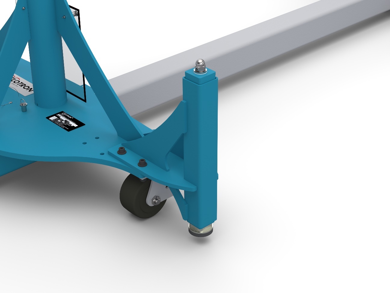
Optional Leveling Jacks (J5):
(Quantity 4) bolt-on Leveling Jacks allow for leveling of the Flotron Rotation Fixture (with payload integrated) while in a stationary position. Code J5 is for Jacks which have a hex driver, and uses a standard wrench (not supplied) to crank up or down. The Jacks have 1″ of rise for each 10 turns of the hex drive. Depending on which caster option is selected, the amount of ground clearance varies when the Leveling Jacks are fully extended or fully retracted. See the proposal drawings for more information.
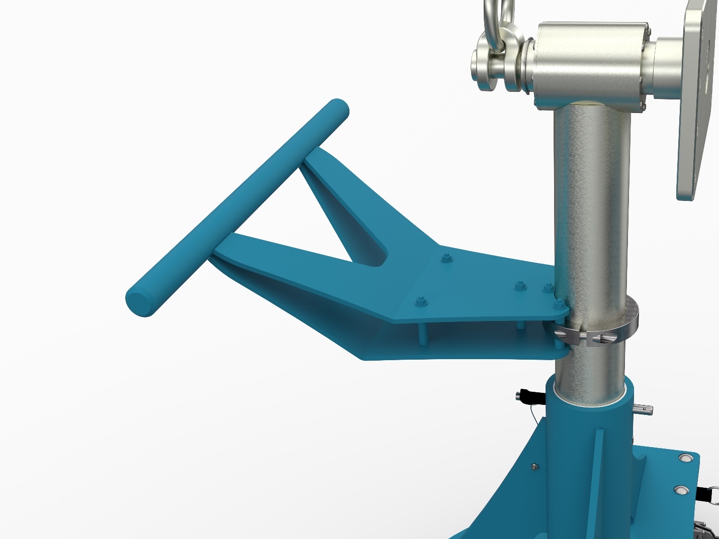
Optional End Frame Mounted Push Bar (P1):
The push bar mounts onto the end frame. Push handle is large enough to be used…. The combination of the swivel locks engaged on the rear casters and a push handle for leverage can make a huge difference to ease transportation. The end frame-mounted push bar can be retrofitted on existing Flotron Rotation Fixtures.
Gearbox:
Standard 60:1 ratio (Blank) – The 60:1 ratio non-back-driving gearbox is the ideal choice if your payload CG is close to rotation centerline. The rated output torque for this gearbox is 7,500 in-lbs and the max CG offset from rotation centerline at rated capacity is 3”. However, the max torque on the gearbox output shaft to maintain “easy crank” (requiring less than 12 lbs of force on the gearbox input shaft hand crank handle) is 2000 in-lbs.
300:1 ratio (DR3) – The double reduction 300:1 ratio gearbox has the same torque rating as the standard gearbox, however the “easy crank” torque increases to 7,200 in-lbs (2.88” CG offset from trunnion centerline). This gearbox is also more stair-step (stick slip) resistant for high inertia payloads. See technical section for more information on stair-stepping.
600:1 ratio (DR6) – The double reduction 600:1 ratio gearbox has the same output torque rating as the standard gearbox and is recommended for the cordless hand drill input (D option) to get manageable output speeds of ½ RPM. Since the easy crank only increases from 7,200 (DR3) to 7,500 in-lbs (3” CG offset from trunnion centerline), it is not recommended for hand crank applications unless the CG offset is very close to 3” or for very high inertia payloads to prevent stair-stepping (stick-slip). See technical section for more information on stair-stepping.
Cordless Hand Drill Input (D):
In lieu of a standard hand-wheel, a battery-powered rechargeable hand drill is mounted to the gearbox input shaft. This option includes an anti-rotation plate with set screws to lock the drill into place so that the technician simply squeezes the trigger to rotate the payload. With this option, easy crank torque is no longer relevant and the full torque rating of the gearbox can be utilized. This option includes a pre-set clutch (in addition to the clutch built into the hand drill) so that the technician doesn’t need to worry about over-torqueing the gearbox. If the payload torque exceeds the rated gearbox torque rating, then the user will hear a clicking sound when operating the hand drill and the payload will not rotate. This option is recommended if rotational duty cycles are high. This option is only available with the DR6 gearbox option.
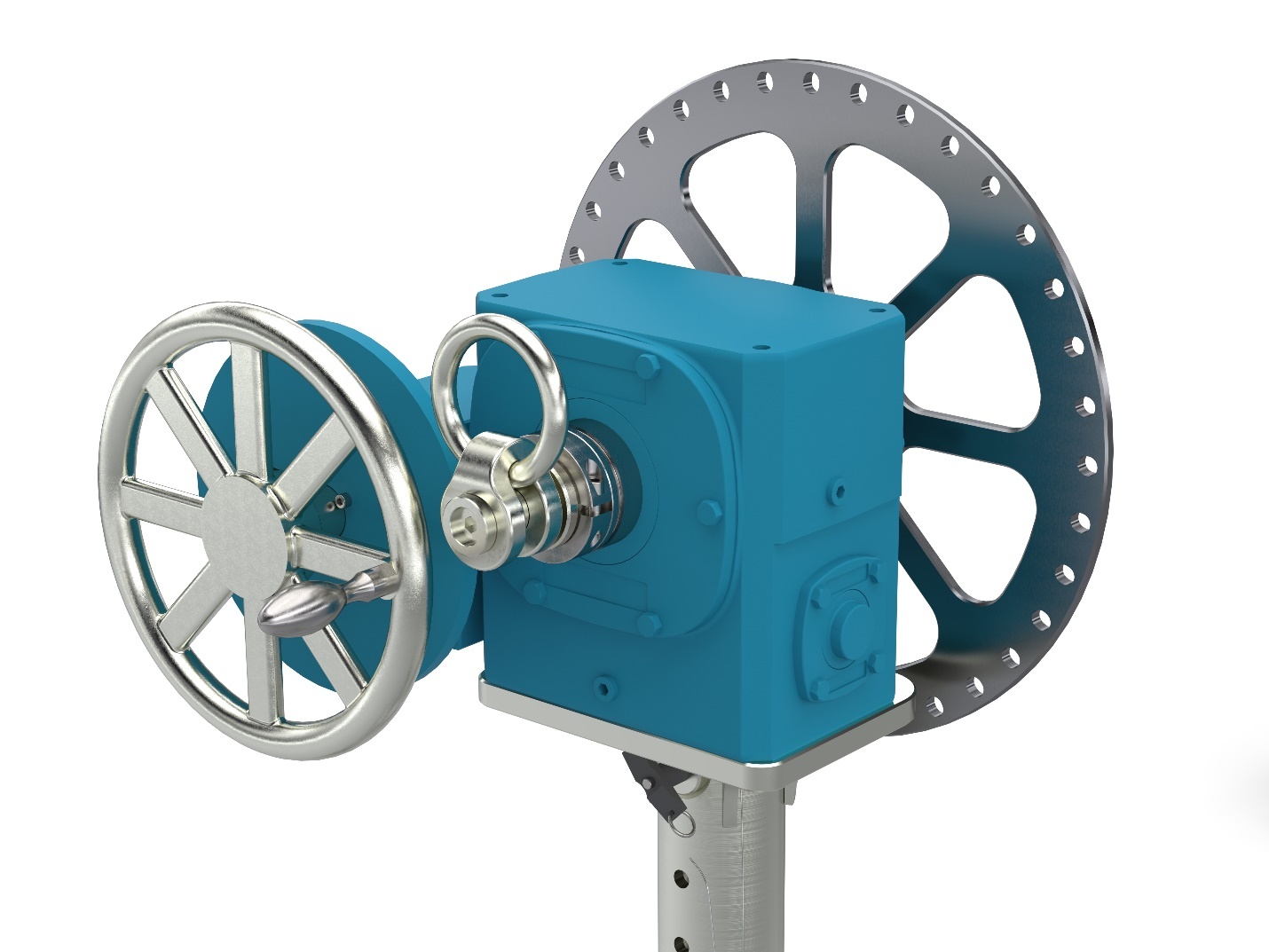
Optional Index Plate
(IND15) –The standard Index Plate is indexed @ 15-degree increments to prevent trunnion rotation with a lock pin. Optional Index Plates can be supplied at special increments as required by the customer.
(INDS15) – This is the same as the standard index plate, but with two Index Stops which can be bolted into any of the indexing holes in the Index Plate to prevent rotation beyond a desired point. This is desirable if the payload has the potential to hit the Flotron main beam, the floor, or any other obstacle when rotated.
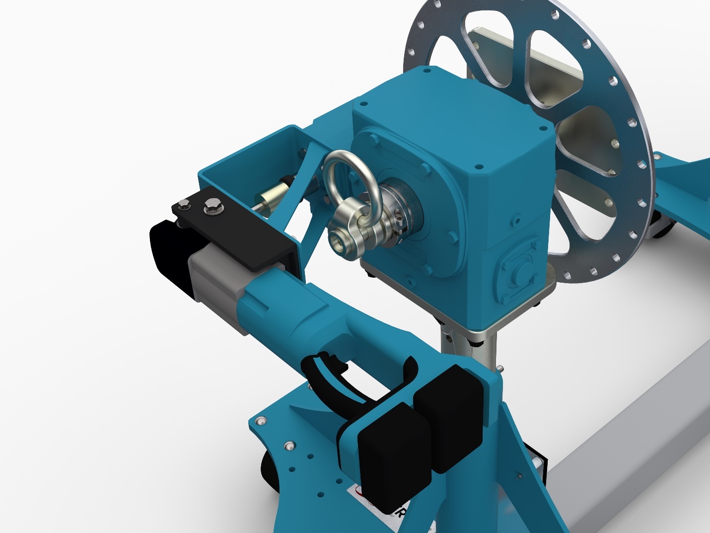
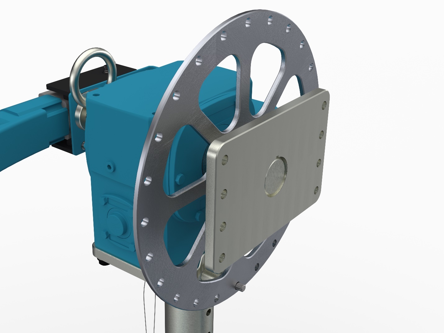
Optional Trunnion Interface Mounts:
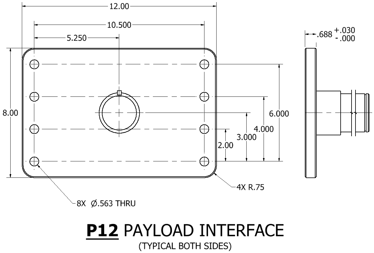
Mounting Plate Interface (P12) – The P12 mounting plate is 8″ x 12″ with an eight-hole bolt pattern spaced at 10.5″ x 6″ centered on the plate. The (quantity 8) thru-holes will accept up to 1/2” diameter bolts. The standard finish is nickel plating.
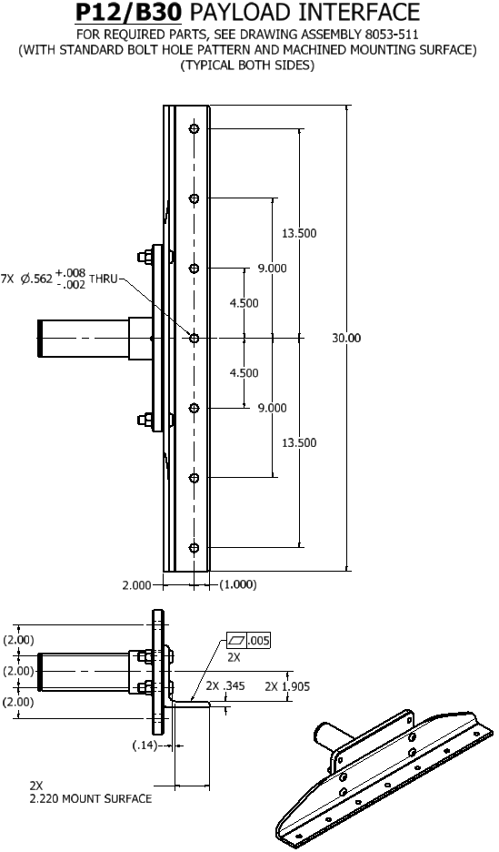
Angle mount interfaces with no mounting holes (P12/A30) – Angle mount interfaces offer the most adaptability. Either the vertical or horizontal surfaces of the angle may be bolted or clamped to. The standard size is 4” x 4” x ¾” thick x 30” long. The standard finish is nickel plating. The (A30) Angles are bolted to the P12 Mounting Plates, which may be removed if it is preferred to mount to the P12 mounting plates. Note that when the angle interface option is chosen, the “B” distance (distance between interface mounts) is measured from the inside vertical faces of the angles.

Angle interface with a standard mounting hole pattern (P12/B30) – This option is the same as the P12/A30 option but with the addition of (quantity 7) Ø0.563 through holes for ½” fasteners. Note that when the angle interface option is chosen, the “B” distance (distance between interface mounts) is measured from the inside vertical faces of the angles. This is still true for the (B30) option so the distance from the hole pattern on one angle to the hole pattern on the other angle will be 3.25” less than the “B” distance.
Interface Distance (BXXX):
Main beams may be ordered with lengths that result in an interface distance that is within the limits shown below. “XXX” = Length in inches between the trunnion interface mounts (1″ increments).
| MODEL | MIN | MAX |
| SFP-747 | 30″ | 280″ |
| SFP-759 | 40″ | 280″ |
Lengths longer than MAX shown above require a special main beam.
While the two end frames can be adjusted inward to accommodate smaller length payloads, the main beams will protrude outside of end frames and can result in a trip hazard. It is therefore desirable to specify an interface distance that is close to the payload length.
Lengths shorter than the MIN shown above will result in stability (tip-over) less than 0.5G.
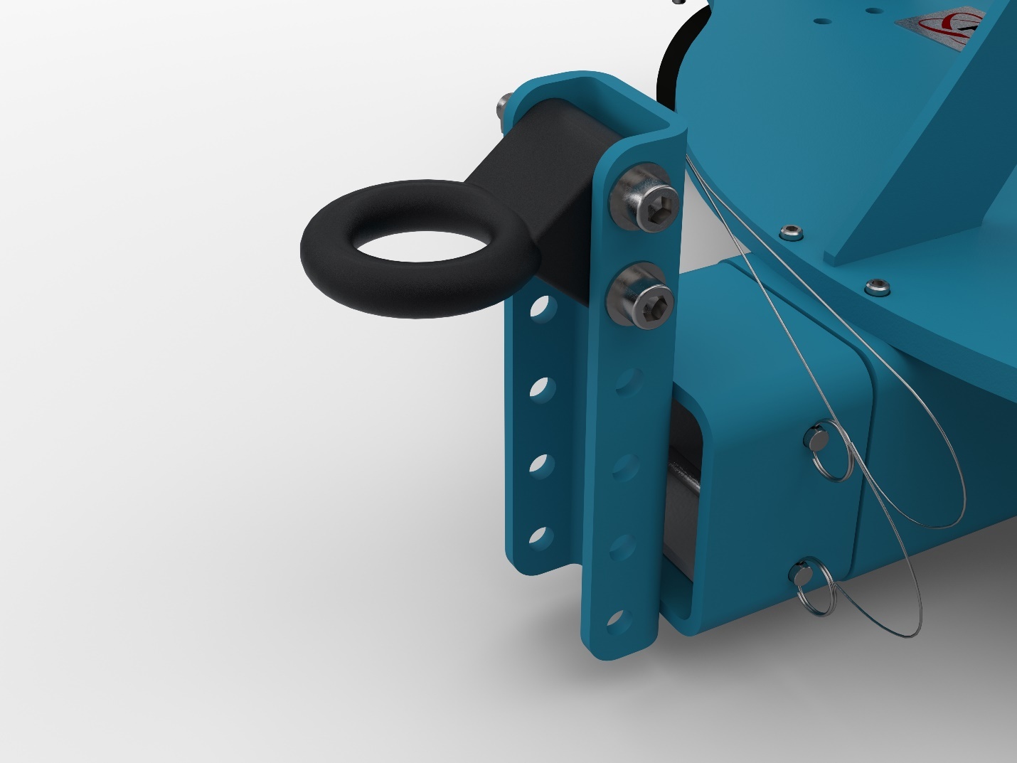
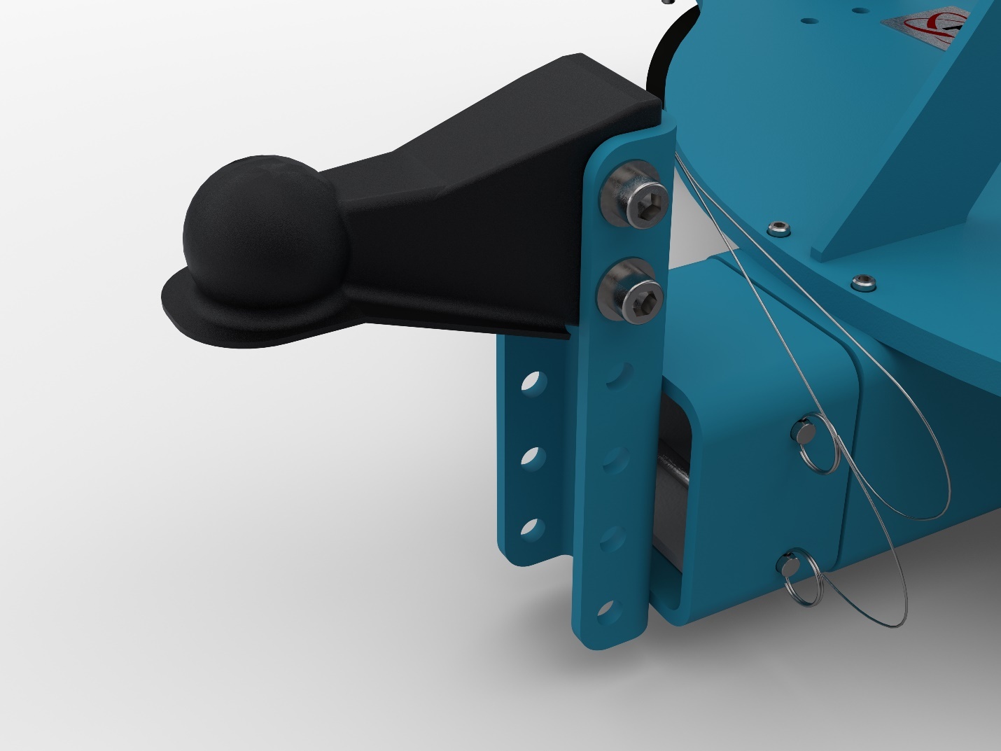
Optional Towing Interfaces:
For the (T1) & (T2) options, a removable towing insert is mounted to the main beam via two ball lock pins. Attached to the towing insert is either a lunette ring (T1) or ball coupler (T2), depending on what option is chosen. The Tow ring’s height can be adjusted in 2-inch increments by changing its position on the C-channel. The towing interface option can be retrofitted on existing Flotron Rotation Fixtures by drilling two holes for the locking pins. The (T3) option is a traditional style tow bar and can also be easily removed via two ball lock pins. For more dimensional information on the towing interface height ranges, see the proposal drawing.
Removable lunette ring towing interface (T1) – The lunette ring has a standard eye that is 4.5” OD and a 2.5” ID and is 1” thick. The towing insert ring assembly attaches to the end of the main beam.
Removable ball coupler towing interface (T2) – The ball coupler accepts a Ø2” ball. The towing inert coupler assembly attaches to the end of the main beam.
Removable tow bar (T3) – The tow bar is a great choice when space is a premium as it won’t increase the overall length of the Flotron Rotation Fixture when in the stowed position.

Optional Casters:
(Blank) – Standard Ø6” X 3” wide Nylon casters with brakes & swivel locks (no steering bars)
(C1) – Ø8” X 3” wide Nylon casters with brakes & swivel locks (no steering bars)
Standard Proof Load Test (PLT):
Proof Load Test Procedure:
Dead weight load (no rotation), visual inspection
- Static proof load test.
- Vertical load only.
- 200% vertical load, 100% torque.
- Hold load for 5 minutes minimum.
- Customer may witness test.
- Paint and plating covers all welds.
- Visually inspect for cracks, deformation, etc.
A deliverable proof load test report will be provided. The report will include a summary of the test procedure, the actual measured weight of load applied, visual inspection results, and images of the test being performed.
Special Options:
If a standard Holding Fixture does not meet your requirements, contact Flotron about custom modifications. Often minor modifications to a standard unit are all you will need and can be done cost-efficiently. See here for past examples of our Modified Standards and Custom Solutions.
For SFP-700 Series – Creating a Model Number, click here.