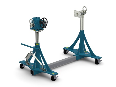
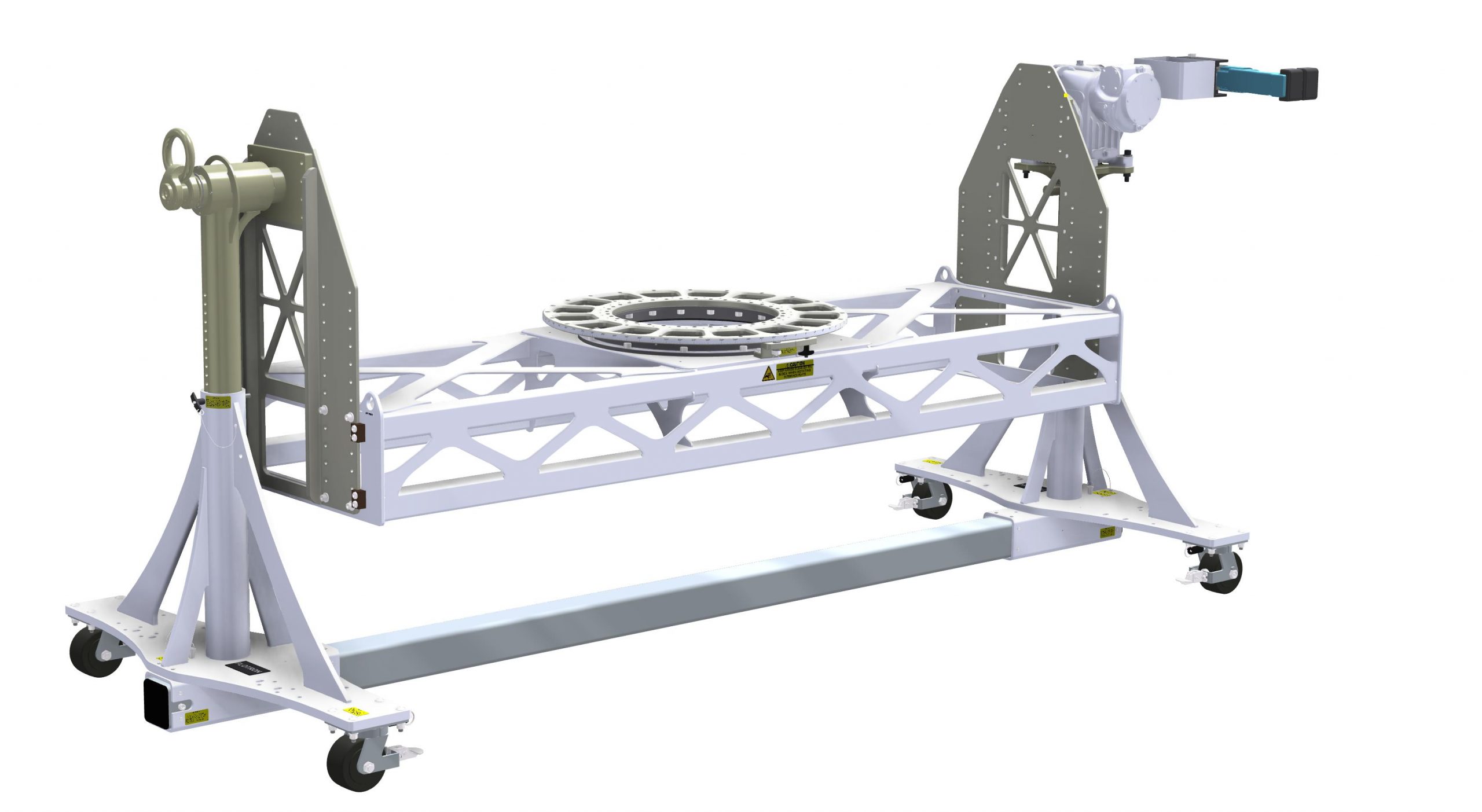
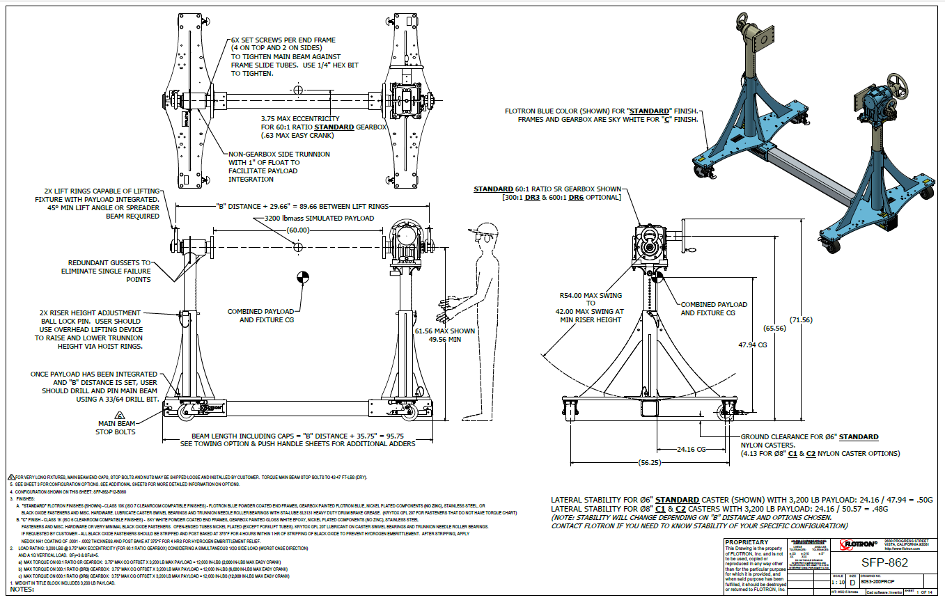
SFP-862
Load Rating (Single Axis): 3200 lbs
Load Rating (Dual Axis): 2,500 lbs (see dimensional drawing sheets 10-13 for load curves)
Swing Radius (Single Axis): 42-54”
Swing Radius (Dual Axis): 58.5”
Max Torque (Primary Axis): 12,000 in-lbs
Easy Crank (Primary Axis): 2,000-12,000 in-lbs
To receive a CAD model or a quotation:
Product Features
- Safety Factor: 3 for Yield & 5 for Ultimate
- Rated Load Capacity:
- Dynamic, 0″ to 3.75″ eccentricity: 3,200 lbs. (1,455 kg.)
- Operating Temperature:
+32 to +104 °F (0 to +40 °C)
- Contact factory for special applications with extended operating temperatures.
- Main Beam Ball Lock Pin: Reliably prevents End Frames from slipping on Main Beam
- Materials: Steel construction
- Axial Float & Sleeve Bearing in Non-Gearbox Side Trunnion: The non-gearbox side trunnion has one inch of axial float to ease payload integration as well as needle roller bearings to increase bearing life and reduce friction.
- NOTE: A smaller than standard swing radius may be recommended for some applications. See the “Holding Fixture Safety” section in Documentation concerning section 4 unexpected accident loads referring to “Maximum Recommended Swing Radius “.
Standard Configuration (For additional options click on “Configure a Flotron Fixture” button above or view dimensional drawing for detailed information)
- Finishes: Class 10k (ISO 7 cleanroom compatible finishes) – Flotron blue powder coated end frames, gearbox painted Flotron blue, nickel plated components (no zinc) stainless steel or black oxide fasteners and mis. hardware. Standard lubricants.
- Main Beam: Single beam that connects the end frames.
- Gearbox: Low backlash, non-back-driving, stair-step resistant, hollow shaft design with 60:1 ratio and 12″ diameter hand crank
- Trunnion Interface/Mount/Clamp Options:
- P12 Mounting Plate (8” x 12”) with a standard mounting hole pattern.
- Axial Float & Sleeve Bearing in Non-Gearbox Side Trunnion: The non-gearbox side trunnion has one inch of axial float to ease payload integration as well as a PTFE composite sleeve bearing to eliminate grease migration, increase bearing life and reduce friction.
- Casters: Ø6″ x 3″ wide Nylatron wheels, king-pin-less swivel bearings, brakes and swivel locks.
- Choice of Main Beam Length
- Combination P12 Mounting Plate / Angle Interface
- Index Plate: Standard with 15° index plate and index stops
- Main Beam Ball Lock Pins: Reliably prevents End Frames from slipping on Main Beam
- A smaller than standard swing radius may be recommended for some applications. See the “Technical Section” under “Holding Fixture Safety” on page 3 of 7 concerning “Unexpected Accident Loads” and the chart on page 4 of 7 referring to “Maximum Recommended Swing Radius“.
- Optional main beam lengths
- Optional leveling jacks
- Optional finishes for clean room compatibility
- Optional lubricants
- Optional forklift tubes
- Optional gearbox mounted push bar
- Optional gearbox ratios
- Optional towing interface
- Optional towing interface
- Optional proof load test
- Optional battery powered hand drill mounted to gearbox input shaft
- Optional ground lug and drag chain for use in electrostatically protected areas (EPA’s)
- Choice of Interface "B" distance: Distance between interfaces. See dimensional drawing for how angle interface distances are measured if angle interface is chosen.
- Casters: Ø6″ x 3″ wide Nylon wheels, kingpinless swivel bearings, brakes, and swivel locks.
As Flotron is constantly improving products and methods of manufacturing, we reserve the right to modify and/or change design or specifications without notice. Please contact Flotron for verification of critical dimensions and specifications.
For SFP-800 Series - Creating a Model Number pdf click here.
For clarification of terms or phrases, please see the Holding Fixtures Definitions page.


