635 Series Standard Options:
Optional Fixture Finishes (N), (C):
- Electroless nickel plating (N): This option replaces all zinc-plated parts with either electroless nickel-plated parts or stainless steel parts.
- Clean Room option (C): This option is identical to the (N) option but with the addition of electroless nickel-plating on the interior of the end frame slide tubes and vertical support tubes. The exterior of the gearbox as well as the exterior of the end frames are painted with high gloss urethane or epoxy paint in place of the standard textured enamel paint.
Optional Ground Lug and Drag Chain (E):
For use in electrostatically protected areas (EPA's). Proper electrostatic discharge (ESD) grounding of the fixture must be a part of the overall EPA design. (See Technical section discussion on ESD.
Optional Lubricants:
Krytox GPL 207 (L1) – The trunnions and caster swivel bearings are lubricated with Krytox GPL 207. Note that this lubricant comes standard on “C” (Clean Room) finish and does not need to be specified.
Braycote 601EF (L2) – The trunnions and caster swivel bearings are lubricated with Braycote 601EF.
Optional Battery Power for Electro-Mechanical Lift Option (BAT):
A battery can be added to power the electro-mechanical lift fixtures. This reduces the need for a power cable to be plugged in during use. This may be useful in areas where cables pose a trip hazard, get in the way, or where electrical outlets are far away. The control box will periodically need to be plugged in to re-charge the battery. The operator can expect to get approximately 5-10 (depending on model) full stroke up/down cycles under max load before charging is necessary. Under lighter loads or partial stroke, the battery can go much longer before charging is necessary. There are light bars on the unit that indicate remaining capacity.
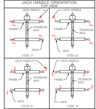
Optional Leveling Jacks (J0, J1, J2, J3 OR J4):
1.4 bolt-on Leveling Jacks allow for leveling of load while in a stationary position. Orientation of jack handles relative to the frame must be specified. See the JACK HANDLE ORIENTATION TABLE below to determine which handle orientation suits your application. Codes J1 through J4 are shown. Code J0, which is not shown, is for jack mounting plates only but does not include jacks. The J0 option allows for future addition of jacks. The Jacks have 1" of rise for each 8 turns of the crank handle.
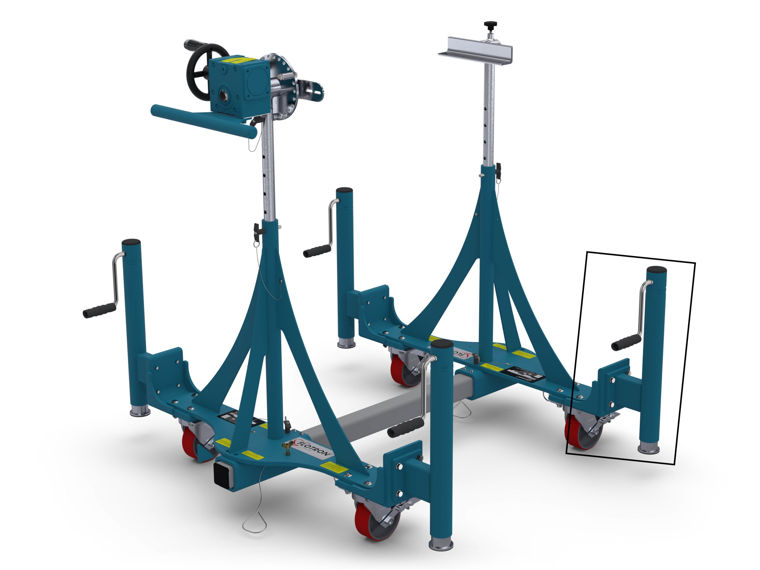

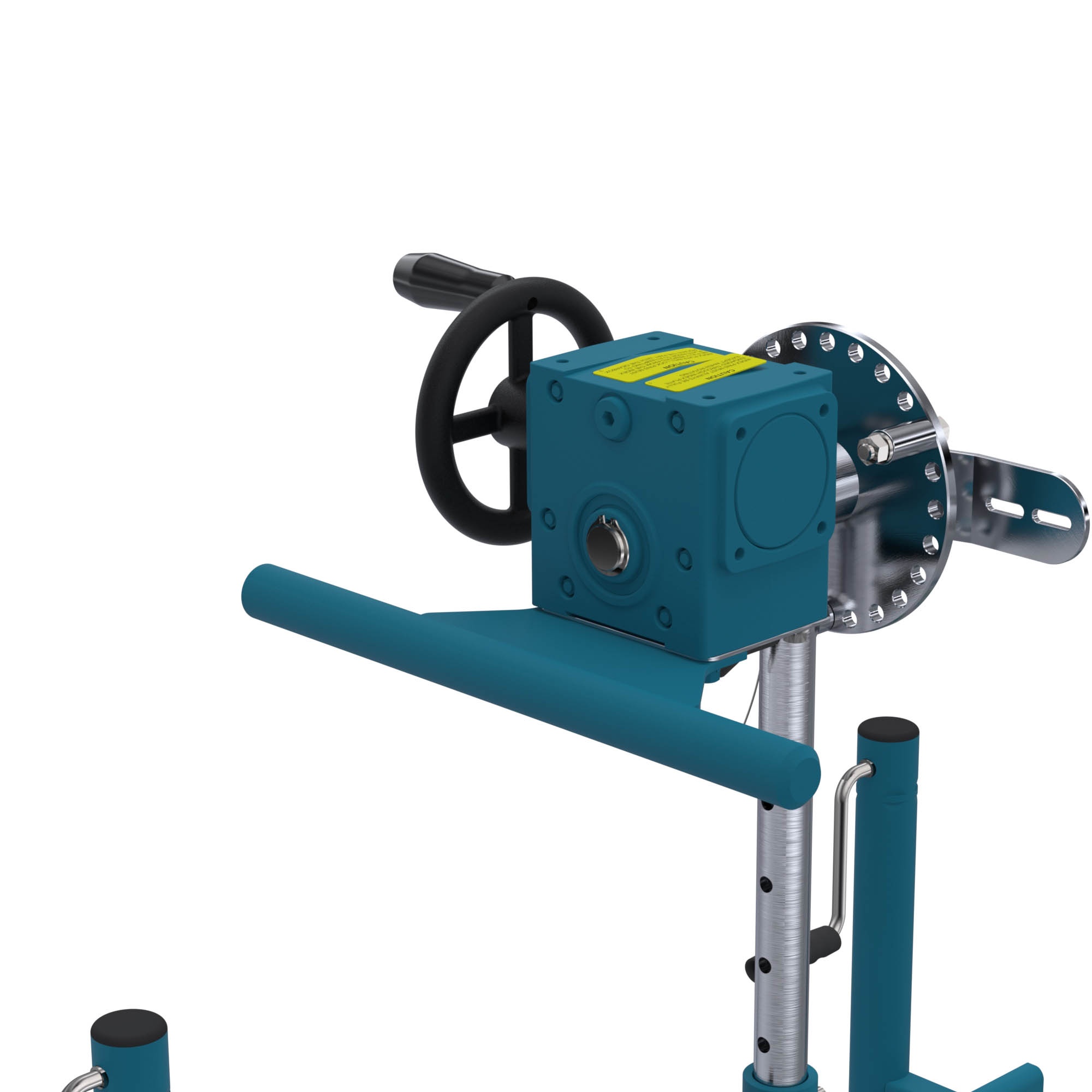
Gearbox Mounted Push Bar (P1):
The push bar is mounted underneath the gearbox and improves ergonomics of intra-facility transport of the Flotron. The combination of having swivel locks engaged on the rear casters and a handle for leverage can make a huge difference to ease transportation. The gearbox mounted push bar can be retrofitted on existing Flotron Rotation Fixtures.
Optional Index Plate (IND15):
Indexed @ 15° increments to prevent trunnion rotation with a lock pin. An Index plate can be supplied with either of the mounting interfaces, shown below or the SA10 angle interface.
Optional Trunnion Interface/Mount/Clamp:
1. Angle Interface (SA10) – The Angle Interface offers the most adaptability for customers. Either of the 2″ perpendicular surfaces of the angle may be bolted or clamped to. The standard length is 10 inches with no bolt holes. The standard finish is clear zinc plate.
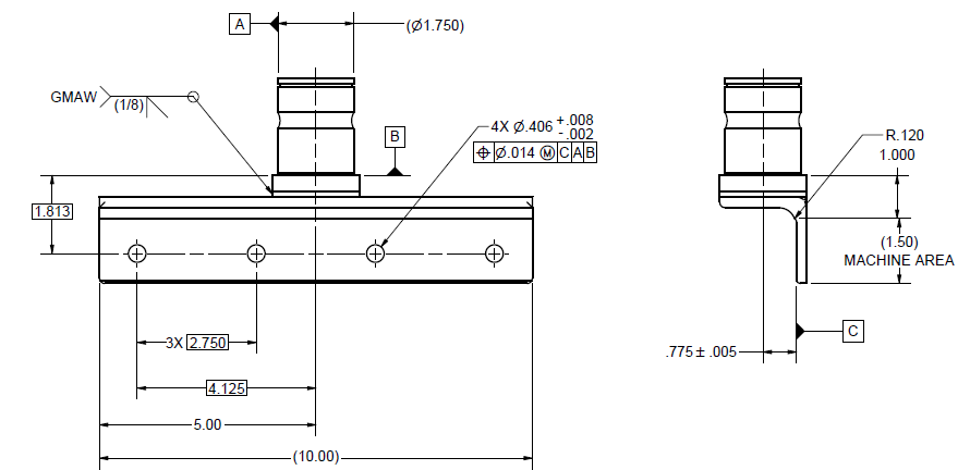
2. Angle Interface (SB10) – The Angle Interface offers the most adaptability for customers. Either of the 2″ perpendicular surfaces of the angle may be bolted or clamped to. The standard length is 10 inches with 4 bolt holes, see drawing down below. The standard finish is clear zinc plate.
3. Mounting Plate Interface (1018) – The part-to-be-handled can be easily bolted to this flange type interface. The standard size is 2″ by 12.5″ with a slotted-hole bolt pattern centered on the plate. The four holes will accept up to ¼” diameter bolts. The standard finish is clear zinc plate.
4. Board Clamp Interface (1023) – The Board Clamp Interface is a 10″ long 2″ x 2″ angle with two screw clamps. It is very convenient for harness boards and similar shaped loads.
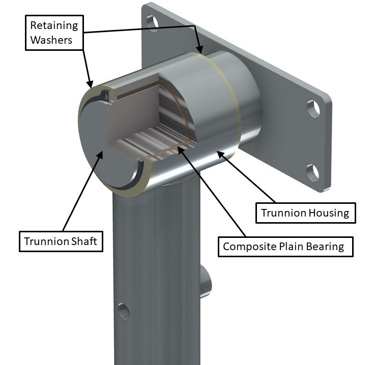
Sleeved Trunnion Bearings (B1):
PTFE composite plain bearing is placed between the trunnion shafts and bearing housings on both vertical risers. The bearings are self-lubricating and therefore do not require any maintenance, prevent wear of the trunnions, and lower rotational friction. This option is recommended when rotational duty cycles are high (frequent rotation), when there is a long interface distance (over 100”), or when the payload is relatively flexible and sags in the middle.
Interface Distance (BXXX):
B“XXX” = Distance in inches between interface mounts measured from inside vertical surfaces of mounts (within the range below).
| MODEL | MIN | MAX |
| SFP-635 | 30" | 141" |
Lengths shorter than the MIN shown above can be dangerous due to tip over. Lengths longer than MAX shown above require a special beam. While the two End Frames can be adjusted toward each other to accommodate smaller length parts, excessively long beams with a small part will leave the Main Beams extending from each End Frame enough to be inconvenient or a trip hazard. It therefore is desirable to order the Main Beam close to the size of the actual part-to-be-handled.
Optional Telescopic Main Beams (TB):
TB1 - Telescopic Main Beams adjust from 66″ to 104″ between Trunnion Interface Mounts. They will do this without extending beyond the End frames. They can be adjusted down to 26″ between Interface mounts by letting them extend beyond the End frames.
TB2 – Same setup as TB1 option with a range of 105”-140”
Optional Casters:
- (Blank) Standard swivel casters with Tech Lock brakes and Ø5" X 2" wide polyurethane wheels.
- (C1) Heavy duty Impak swivel casters with swivel locks, tread lock brakes and Ø5" X 2" wide polyurethane wheels.
- (C2) Swivel casters with conductive wheels, tech-lock brakes and Ø5" X 2" wide wheels. (not shown)
- (C3) Heavy duty Impak swivel casters with swivel locks, tread lock brakes and Ø5" X 2" wide elastomer wheels to improve rollability. (not shown)
Standard Proof Load Test (PLT):
Proof Load Test Procedure:
Dead weight load (no rotation), visual inspection.
- Static proof load test.
- Vertical load only.
- 200% vertical load, 100% torque.
- Hold load for 5 minutes minimum.
- Customer may witness test.
- Paint and plating covers all welds.
- Visually inspect for cracks, deformation, etc.
A deliverable proof load test report will be provided. The report will include a summary of the test procedure, actual measured weight of load applied, visual inspection results, and images of the test being performed.
Special Options:
If a standard holding fixture does not meet your requirements, contact Flotron about custom modifications. Often, minor modifications to a standard unit are all you will need and can be done cost effectively.
For SFP-600 Series – Creating a Model Number, click here.*