700 Series Standard Options:
Optional Fixture Finishes (N), (C):
1. Electroless nickel plating (N): This option replaces all zinc-plated parts with either electroless nickel-plated parts or stainless steel parts.
2. Clean Room option (C): This option is identical to the (N) option but with the addition of electroless nickel-plating on the interior of the end frame slide tubes and vertical support tubes. The exterior of the gearbox as well as the exterior of the end frames are painted with high gloss urethane or epoxy paint in place of the standard textured enamel paint.
Optional Ground Lug and Drag Chain (E):
For use in electrostatically protected areas (EPA’s). Proper electrostatic discharge (ESD) grounding of the fixture must be a part of the overall EPA design. (See Technical section discussion on ESD.
Optional Lubricants:
Krytox GPL 207 (L1) – The trunnions, caster swivel bearings, and jacks (if applicable) are lubricated with Krytox GPL 207. Note that this lubricant comes standard on “C” (Clean Room) finish and does not need to be specified.
Braycote 601EF (L2) – The trunnions, caster swivel, and jacks (if applicable) bearings are lubricated with Braycote 601EF.
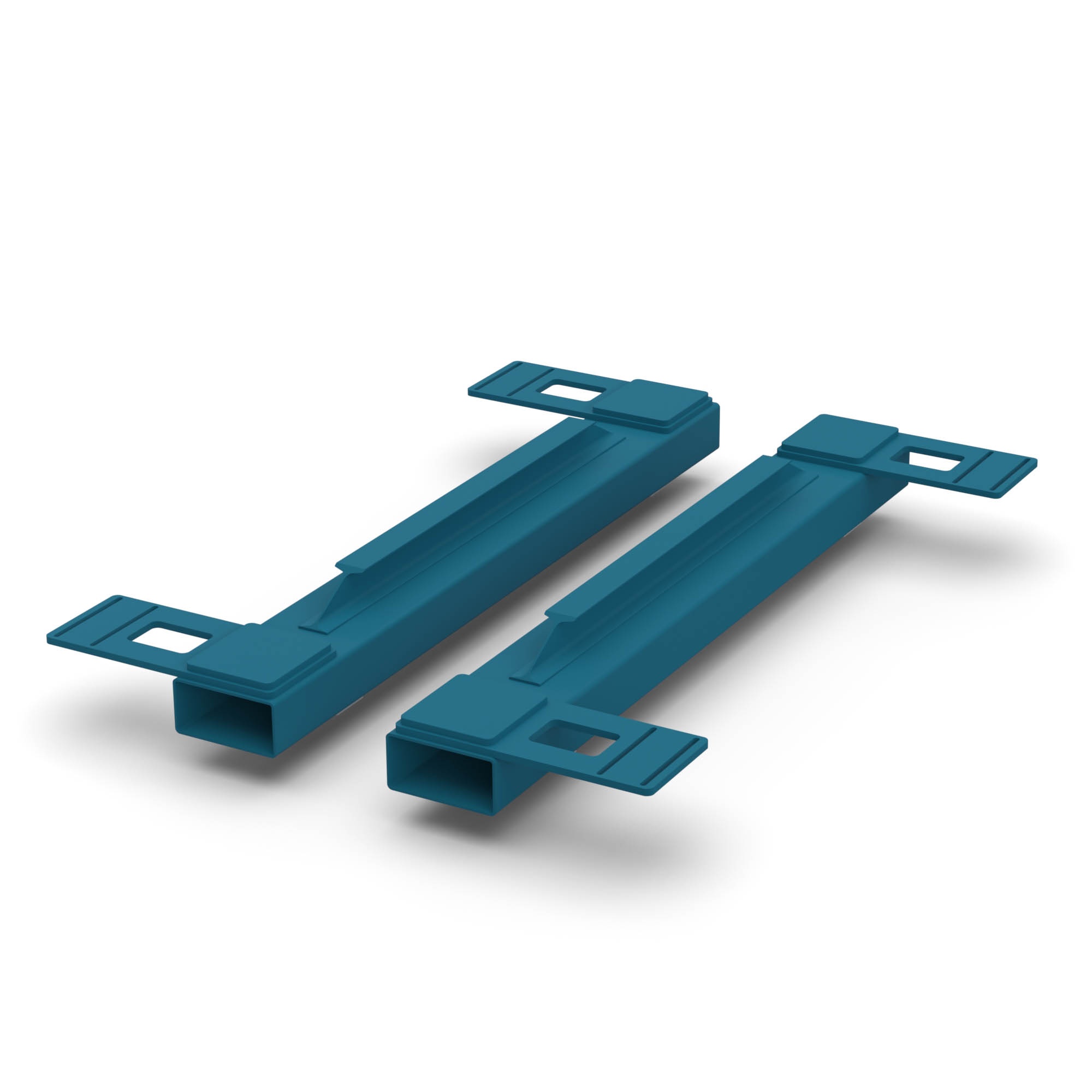
Forklift Tubes (F1):
Forklift tubes are bolted to the bottom of the end frames and span the length of the fixture. They are designed with a stiffener I-beam welded to the top of the forklift tubes so that the forks do not need to span the entire length of the fixture if long enough forks are not available. It is critical that the forks extend at least two feet past the combined fixture and payload CG. If you are unsure of how long the forks need to be for your application, please contact Flotron. The forklift tubes are compatible with all of the 700 series except for the XD739 models. The forklift tube option can be retrofitted on existing Flotron Rotation Fixtures.
Optional battery power for Electro-Mechanical Lift option (BAT):
A battery can be added to power the electro-mechanical lift fixtures. This reduces the need for a power cable to be plugged in during use. This may be useful in areas where cables pose a trip hazard, get in the way, or where electrical outlets are far away. The control box will periodically need to be plugged in to re-charge the battery. The operator can expect to get approximately 5-10 (depending on model) full stroke up/down cycles under max load before charging is necessary. Under lighter loads or partial stroke, the battery can go much longer before charging is necessary. There are light bars on the unit that indicate remaining capacity. 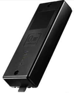
Telescopic Main Beam:
Telescopic Beam (TB1) – Telescopic main beam allows for interface (“B”) distance range of 66”-104” without main beam sticking out past end frames by more than 3 inches. Telescopic Beam (TB2) – Same as TB1 option with an interface distance range of 105”-140”.
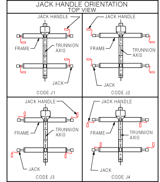
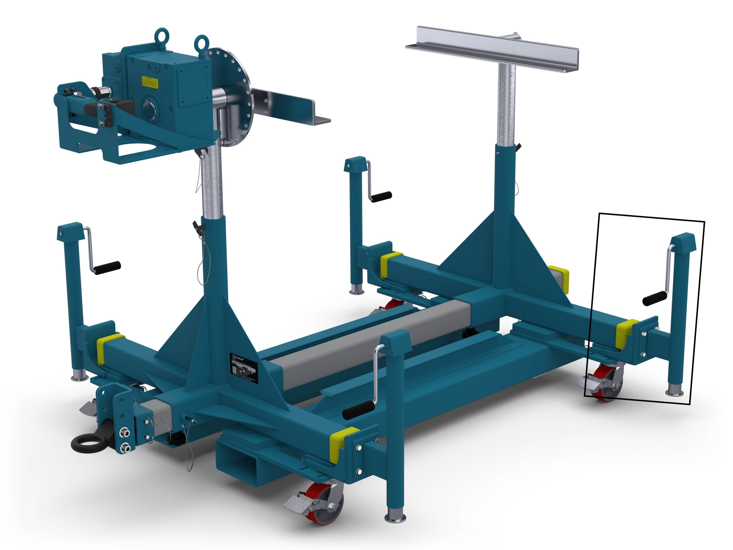
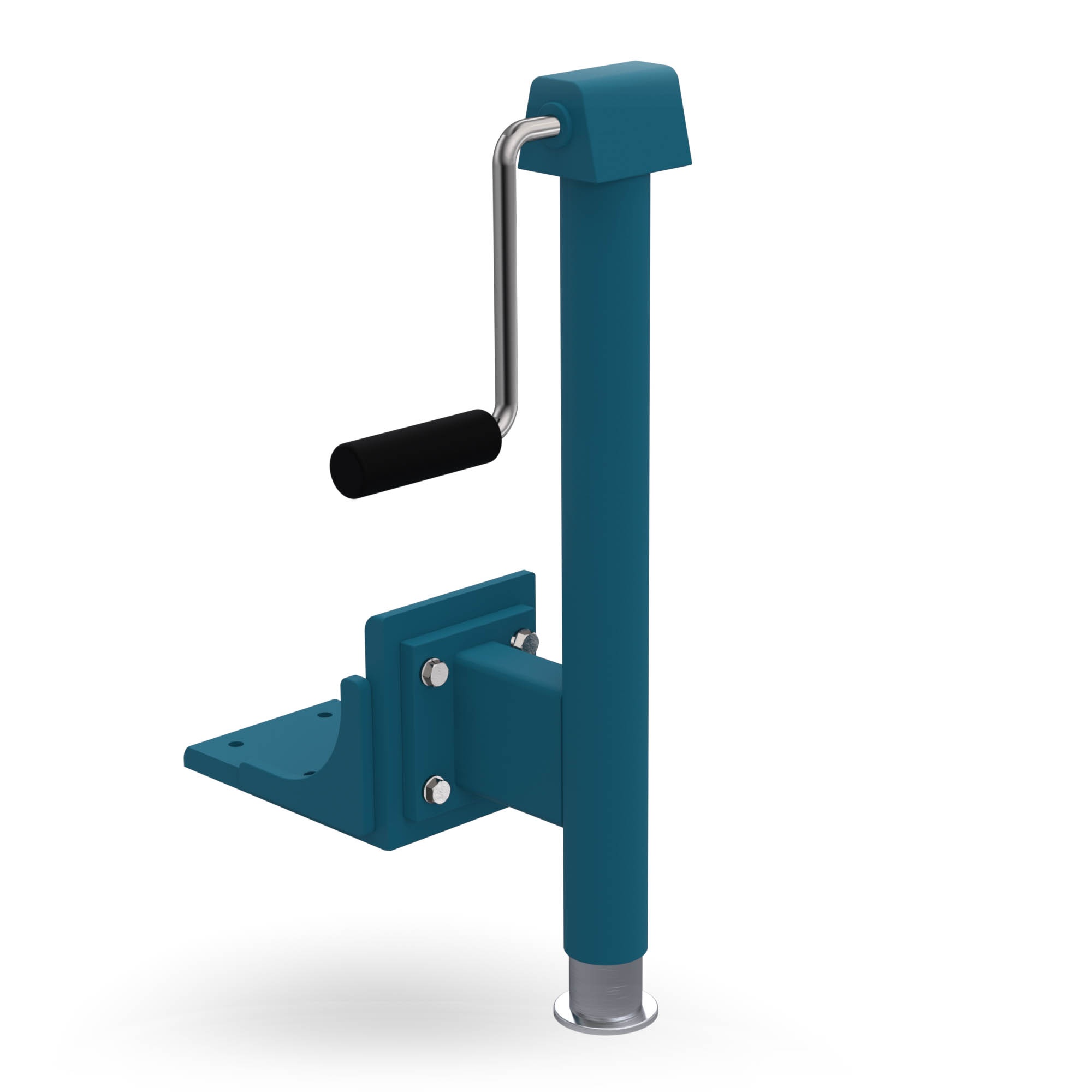
Optional Leveling Jacks (J0, J1, J2, J3 OR J4):
1.4 bolt-on Leveling Jacks allow for leveling of load while in a stationary position. Orientation of jack handles relative to the frame must be specified. See the JACK HANDLE ORIENTATION TABLE below to determine which handle orientation suits your application. Codes J1 through J4 are shown. Code J0, which is not shown, is for jack mounting plates only but does not include jacks. The J0 option allows for future addition of jacks. The Jacks have 1″ of rise for each 8 turns of the crank handle.
Optional Heavy Duty Gearbox:
1. Optional 60:1 ratio Single reduction Gearbox (SR): This gearbox offers heavier duty construction than the standard gearbox, plus low backlash and slightly more resistance to stair stepping. NOTE: Addition of the optional SR or DR gearbox decreases the vertical riser adjustment by 2″. 2. Optional 250:1 ratio Double Reduction Gearbox (DR): This gearbox offers heavier duty construction than the standard gearbox, plus low backlash, 3000 in-lbs easy crank torque (versus the standard 2000 in-lbs easy crank torque), and is immune to stair stepping at nearly all reasonable inertia’s and torques. NOTE: Addition of the optional SR or DR gearbox decreases the vertical riser adjustment by 2″.
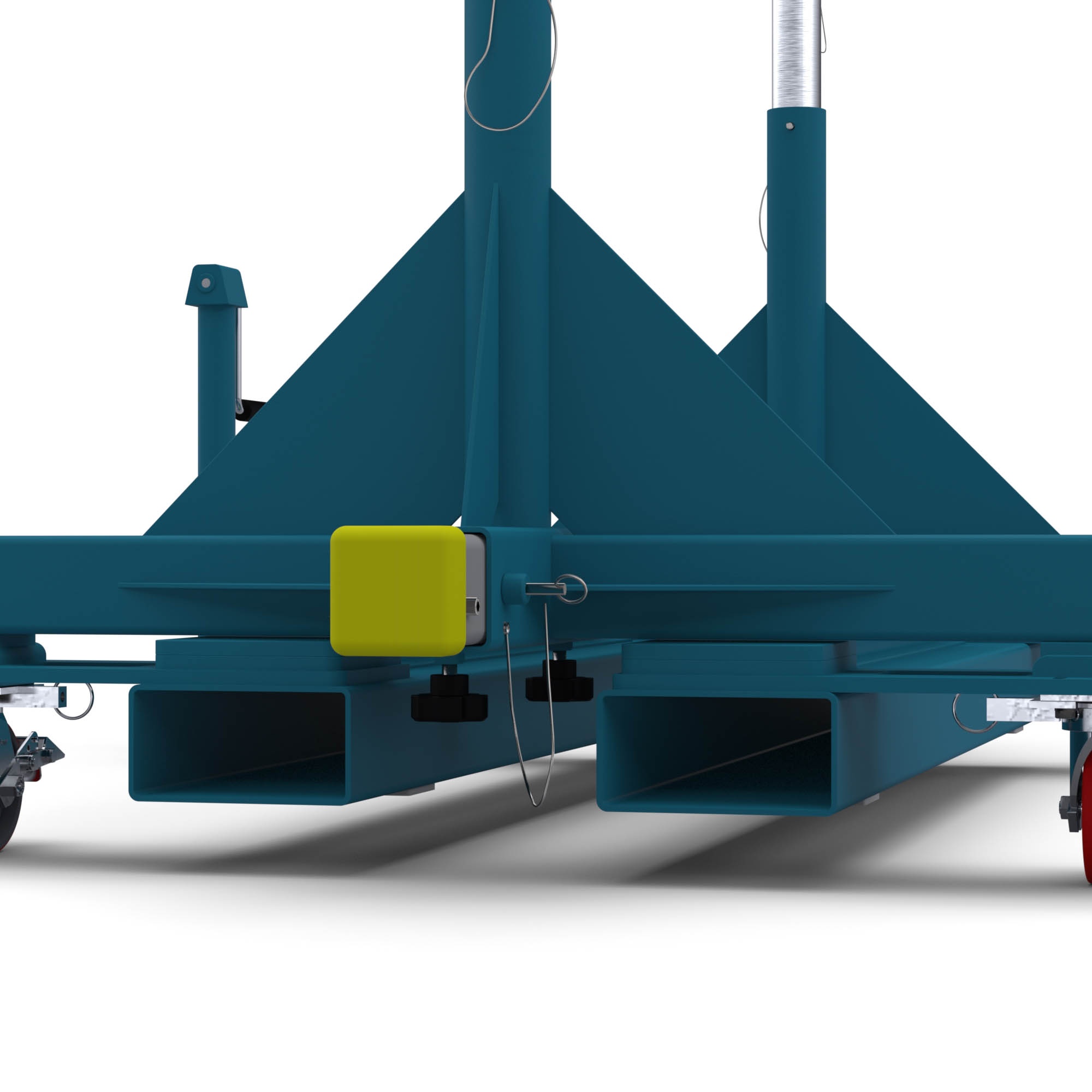
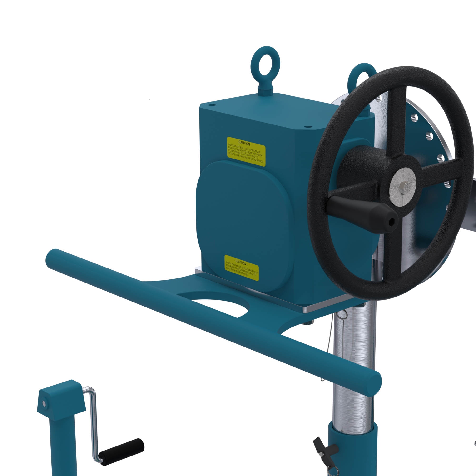
Gearbox Mounted Push Bar (P1):
The push bar is mounted underneath the gearbox and improves ergonomics of intra-facility transport of the Flotron. The combination of having swivel locks engaged on the rear casters and a handle for leverage can make a huge difference to ease transportation. The gearbox mounted push bar can be retrofitted on existing Flotron Rotation Fixtures.
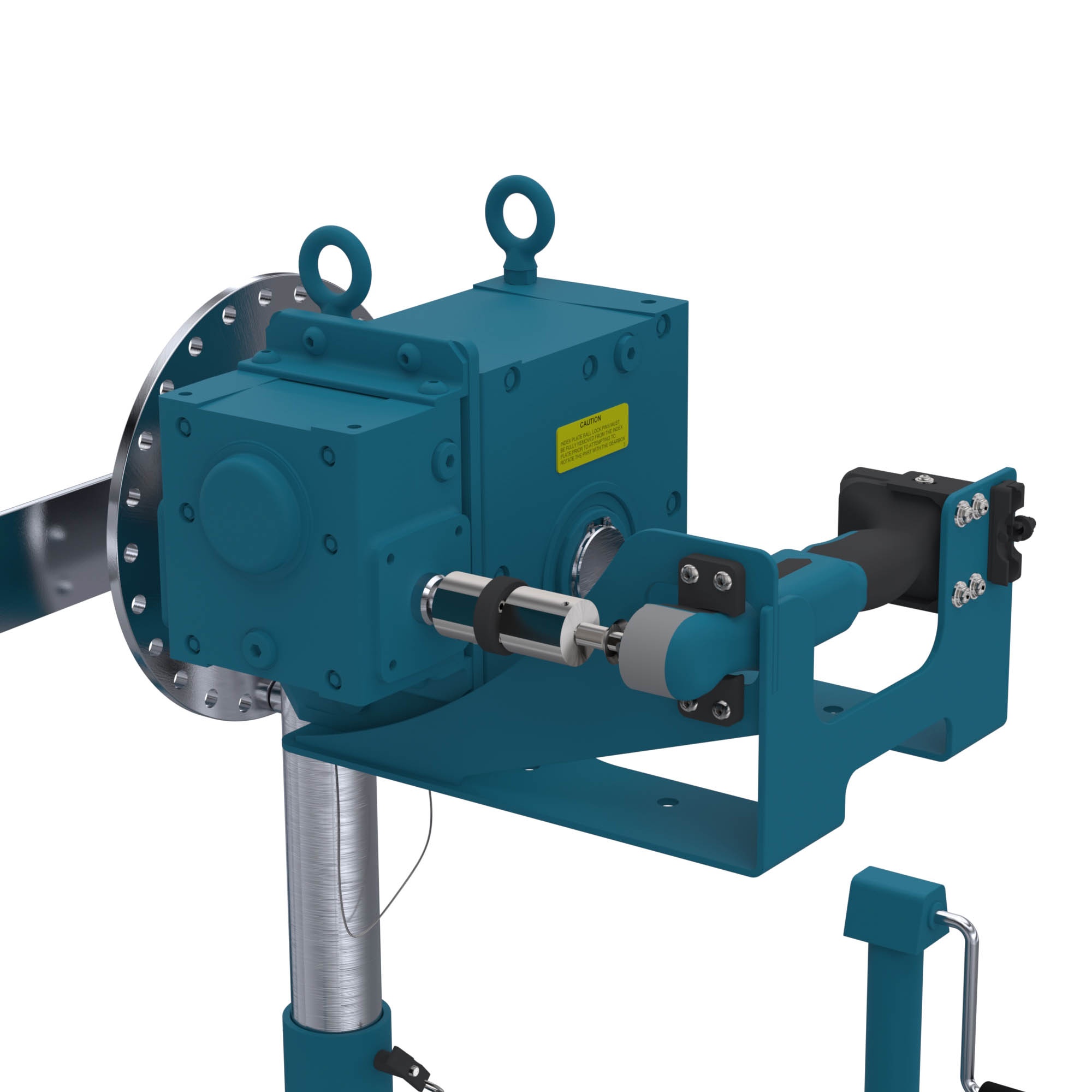
Cordless Hand Drill input (D):
A 12 Volt battery powered right angle drill comes mounted to the gearbox shaft and rotation fixture with attachment brackets. If this option is chosen, the DR gearbox option must also be selected. This drill is capable of 0 – 4.4 rpm output speed of the interface. Since this drill has more torque than can be achieved with a manual handwheel, the full torque rating of the gearbox can be utilized, and the user does not need to worry about easy crank torque ratings. A clutch is also incorporated on the input shaft of the gearbox in case the user forgets to remove the indexing lock pin before rotation.
Optional Index Plate (IND15):
Indexed @ 15° increments to prevent trunnion rotation with a lock pin. The Index plate can be supplied with either the P8 Mounting Plate Interface(shown below) or the A30 Angle Interface, or the P12/A30 Combination Mounting Plate / Angle Clamp.
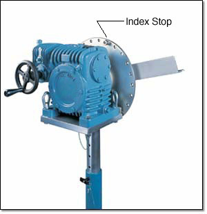
Optional Index Plate with Index Stops (INDS15):
Identical to the IND15 option shown above but with the addition of two Index Stops. The Stops can be bolted into any of the index holes in the Index Plate to prevent rotation beyond a desired point. This can be a desirable option if your part-to-be-handled has a protrudance that could hit the main beam or floor or other obstacle when rotated beyond a certain orientation. 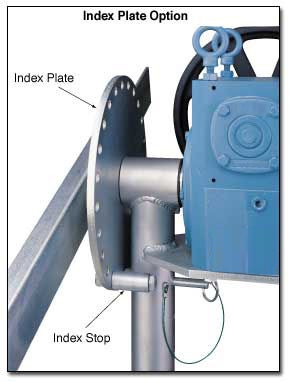
Optional Trunnion Interface/Mount/Clamp:
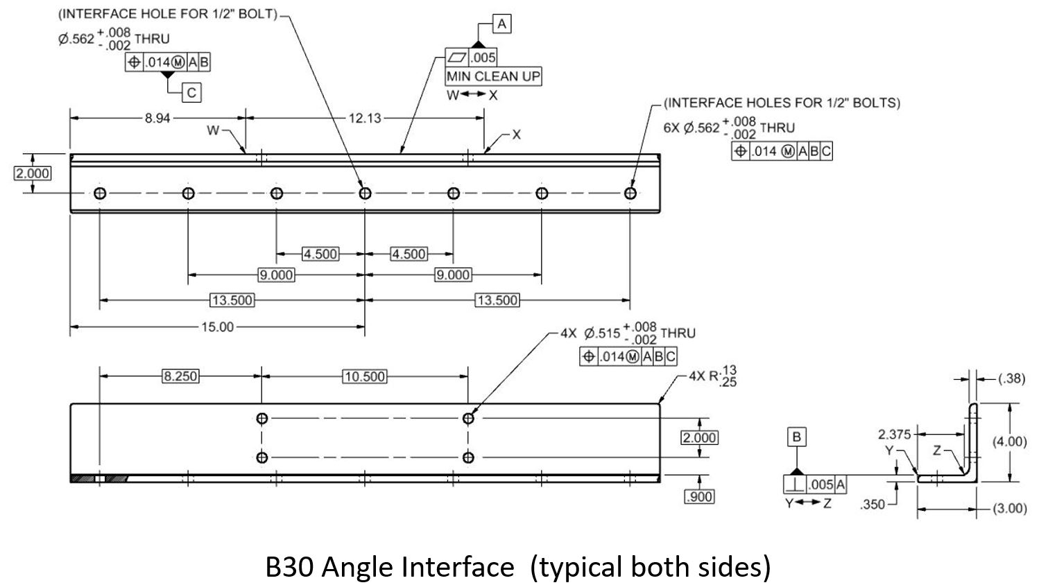
1. Angle Interface (A30) – The angle interface offers the most adaptability for customers. Either of the 3″ perpendicular surfaces of the angle may be bolted to. The standard length is 30 inches with no bolt holes. The standard finish is clear zinc plate. 2. Angle Interface with hole pattern (B30) – This 30” long angle mount has a standard bolt hole pattern on the horizontal surface of the angle so drilling of the angle at assembly is not necessary to install your part. 3. Mounting Plate Interface (P8) (Not available on SR or DR option. See P12/A30 options.) – The Part-to-be-handled can be easily bolted to this flange type interface. The standard size is 3″ by 8″ with a four-hole bolt pattern spaced at 7″ by 2″ centered on the plate. The four holes will accept up to ½” diameter bolts. The standard finish is clear zinc plate.

Optional Combination Mounting Plate / Angle Clamp (P12/A30):
(Available only with SR or DR option) 1. Angle Interface (A30) – The Angle Interface offers the most adaptability for customers. Either of the perpendicular surfaces of the angle may be bolted or clamped to. The standard length is 30 inches with no bolt holes. The standard finish is clear zinc plate. The A30 Angle is bolted to the P12 Mounting Plate and may be removed if the customer desires to mount directly to the P12. 2.Mounting Plate Interface (P12) – The Part-to-be-handled can be easily bolted to this flange type in interface. The standard size is 8″ x 12″ with an eight-hole bolt pattern spaced at 10.5″ x 6″ centered on the plate. The eight holes will accept up to 1/2″ diameter bolts. The standard finish is clear zinc plate. 
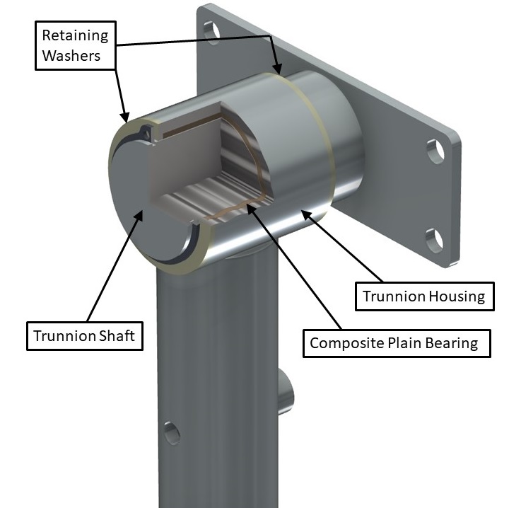
Sleeved Trunnion Bearings (B1):
PTFE composite plain bearing is placed between the trunnion shafts and bearing housings on both vertical risers. The bearings are self-lubricating and therefore do not require any maintenance, prevent wear of the trunnions, and lower rotational friction. This option is recommended when rotational duty cycles are high (frequent rotation), when there is a long interface distance (over 100”), or when the payload is relatively flexible and sags in the middle.
Interface Distance (BXXX):
B“XXX” = Distance in inches between interface mounts measured from inside vertical surfaces of mounts (within the range below).
| MODEL | MIN | MAX |
| 739 | 30″ | 141″ |
| 747 | 37″ | 141″ |
| 759 | 49″ | 141″ |
| 739DB | 30″ | 154″ |
| 747DB | 37″ | 154″ |
| 759DB | 49″ | 154″ |
Lengths shorter than the MIN shown above can be dangerous due to tip over. Lengths longer than MAX shown above require a special beam. While the two End Frames can be adjusted toward each other to accommodate smaller length parts, excessively long beams with a small part will leave the Main Beams extending from each End Frame enough to be inconvenient or a trip hazard. It therefore is desirable to order the Main Beam close to the size of the actual part-to-be-handled.
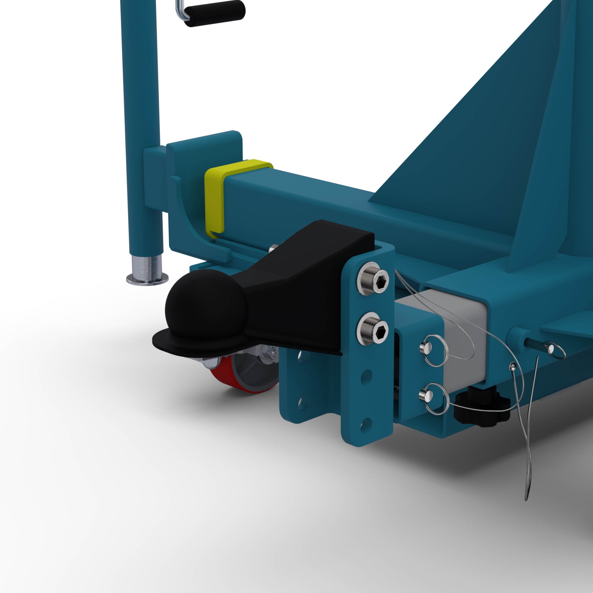
Towing Interface:
A removable towing insert is mounted to the main beam via two ball lock pins. Attached to the towing insert is either a lunette ring (T1) or ball coupler (T2) depending on which option is chosen. The tow ring/coupler’s height can be adjusted in 2-inch increments from 8.25” – 12.25” (as measured from floor to interface centerline) by changing its position on the C-channel and lowered all the way down to 5.25” if the tow insert is flipped upside down. The towing interface option is not compatible with double beam fixtures. If a towing feature is needed for a double beam fixture, it is recommended to add a towbar (modified standard). The towing interface option can be retrofitted on existing Flotron Rotation Fixtures.
A. Lunette Ring (T1) – The lunette ring has a standard eye that is 4.5” OD and a 2.5” ID and is 1” thick. B. Ball Coupler (T2) – The ball coupler accepts a Ø2” ball. 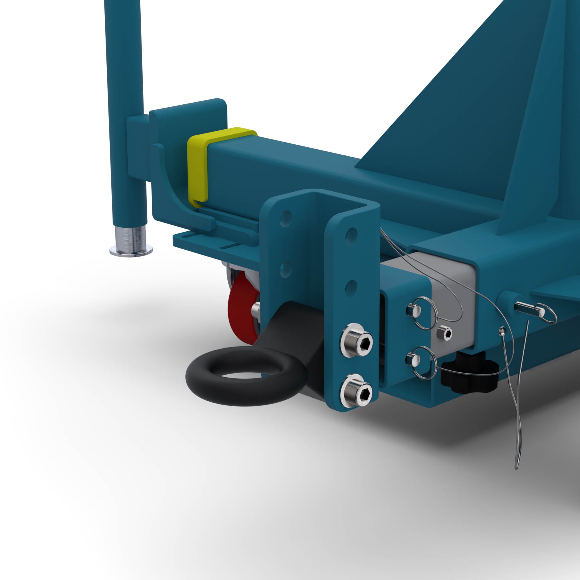
Optional Casters:
- (Blank) Standard swivel casters with Tech Lock brakes and Ø5″ X 2″ wide polyurethane wheels.
- (C1) Heavy duty Impak swivel casters with swivel locks, tread lock brakes and Ø5″ X 2″ wide polyurethane wheels.
- (C2) Swivel casters with conductive wheels, tech-lock brakes and Ø5″ X 2″ wide wheels. (not shown)
- (C3) Heavy duty Impak swivel casters with swivel locks, tread lock brakes and Ø5″ X 2″ wide elastomer wheels to improve rollability. (not shown)
- (C4) Ø5″ X 2″ wide spring-loaded casters with urethane wheels which isolates shock and vibration. Includes swivel locks and brakes. (not shown)
Standard Proof Load Test (PLT):
Proof Load Test Procedure:
Dead weight load (no rotation), visual inspection
- Static proof load test.
- Vertical load only.
- 200% vertical load, 100% torque.
- Hold load for 5 minutes minimum.
- Customer may witness test.
- Paint and plating covers all welds.
- Visually inspect for cracks, deformation, etc.
A deliverable proof load test report will be provided. The report will include a summary of the test procedure, actual measured weight of load applied, visual inspection results, and images of the test being performed.
Special Options:
If a standard Holding Fixture does not meet your requirements, contact Flotron about custom modifications. Often minor modifications to a standard unit is all you will need and can be done cost efficiently. See here for past examples of our Custom Solutions. To configure a 700 series rotation fixture, click here.*