Archives
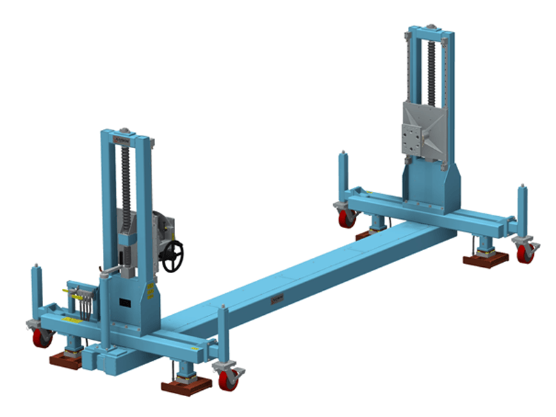
Engineered Lift
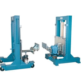
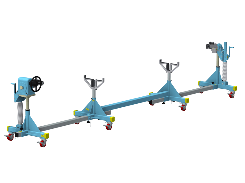
Asynchronous Lift
A Flotron Engineered Manual Composite Layup Lift and Rotation fixture was implemented to support the upper and lower fuselage halves that were originally resting on the floor in this application. Operators were bending over and were literally on their hands and knees reaching to perform their daily process. This Flotron Custom Solution was designed to lift and rotate the long composite payload to minimize workplace injuries and potential damage to high value flight hardware, provide access through ergonomic rotation, and maximize production throughput. A low backlash gearbox provides the rotational functionality and two independent end frames support the payload and lift it with unsynchronized hand-crank rack and pinion lift jacks. The couplings allow for angular misalignment. One of the end frames of this turnover fixture is bolted to the floor and the opposing end frame rolls on tracks that are bolted to the floor, providing flexibility to accommodate varying payload lengths. Custom cradles support the trunnion shafts in their lowest position during the payload loading and unloading process on this Flotron Lift Fixture.
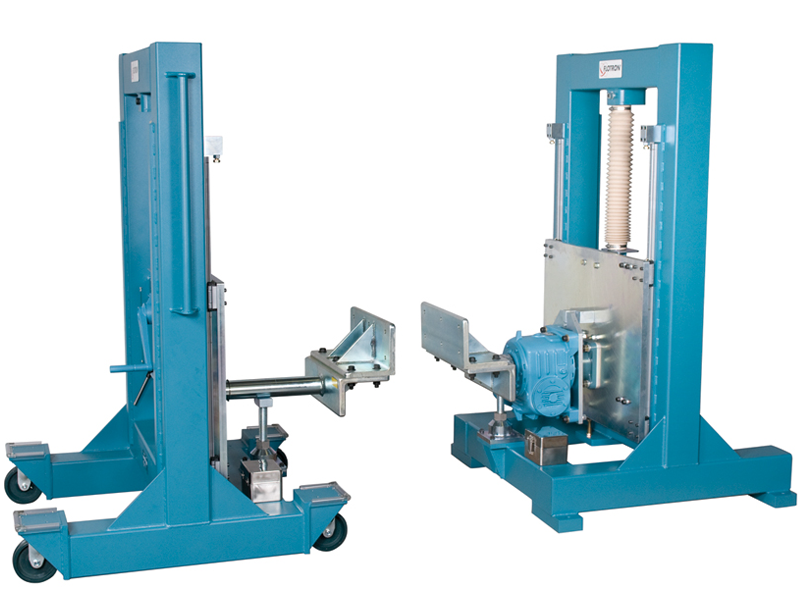
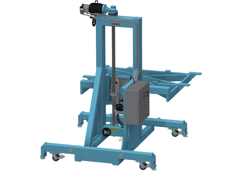
Synchronized Mechanical Lift
Flotron designed and implemented a mechanically synchronized lift system on this lift fixture. With a single input hand crank, an operator can ergonomically raise and lower a 2,000 lbs payload two feet. This 24” height change range is accomplished safely and without back-driving by incorporating redundant brakes in conjunction with ball screw lift jacks. Two carriage plates are guides vertically using precision linear guide bearing rails. In addition to lifting functionality, this aerospace tool is a rollover dolly that provides 360 degrees of ergonomic rotation. Flotron’s mechanically synchronized lift / rotate holding fixture is used to position various aircraft control surfaces at the appropriate height and orientation as the payloads travel through a series of automated drilling processes down a production line on air pallets.
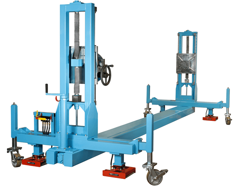
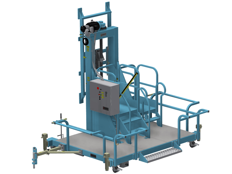
Long-Stroke Leveling Jack Lift
Flotron’s vertical lifting capability has served multiple purposes for our customers ground support equipment needs. In addition to accommodating various operator heights or positioning payloads at critical heights to perform various processes, Flotron’s engineered lift systems are used for vertical integration applications. In this particular case, Flotron incorporated high capacity, long-stroke lift jacks at the four corners of the rotation fixture end frames to lift the fixture (plus 4,000 lbs payload) 15 inches vertically to attach the payload to an overhead platform. Additionally, this Aerospace Tool offers ergonomic rotation to the technician for assembly, integration and test applications. An air pallet system has been incorporated under each of the four lift jacks and transforms this tool into a transportation fixture to maneuver the fixture (with payload integrated) over sealed floor surfaces.
Solar Wing Offload Work Station
Engineered electro-mechanical lift fixture capable of lifting and tilting a large panel stack to be offloaded for deployment.
Solar Wing Deployment Work Station
Engineered electro-mechanical lift fixture capable of lifting, pivoting and deploying a large panel stack.
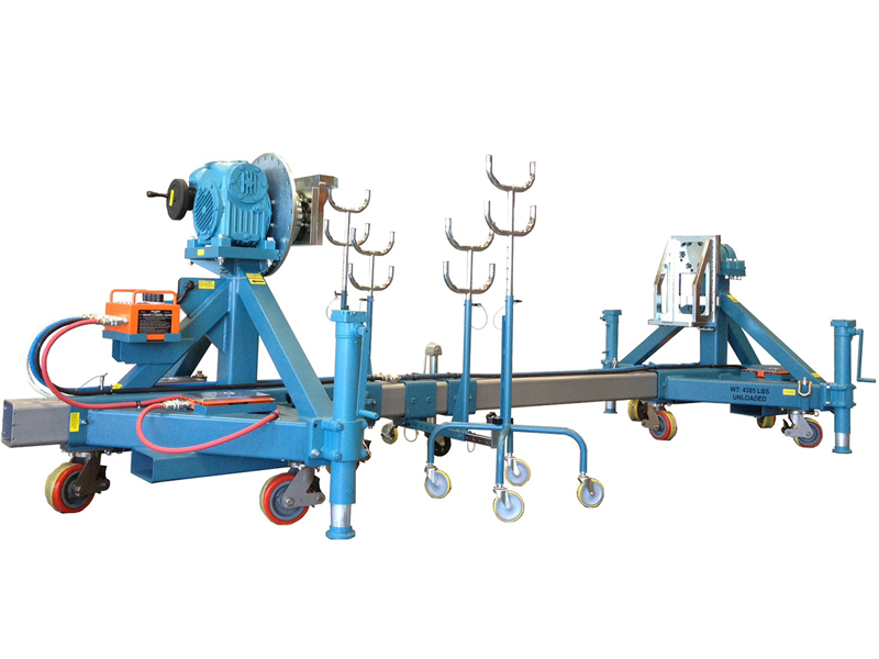
Double Plus Chord Work Station
Asymmetric lift and rotation fixture capable of interfacing and lifting a complex geometry payload to improve safety and ergonomics.
Automated Drilling Fixture
Synchronized mechanical lift and rotation fixture with 2,000 lbs. capacity and air bearing system designed to support an aircraft control surface during an automated drilling operation.
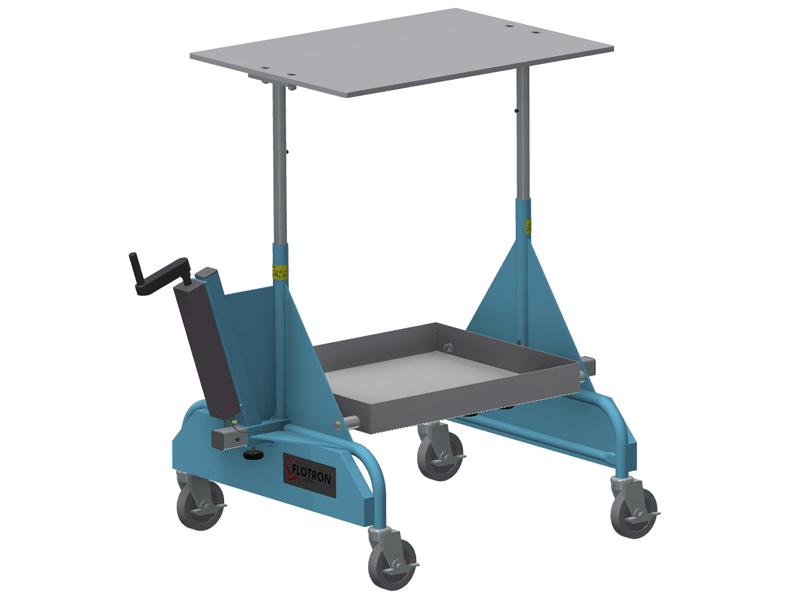
Lifting Platform
Synchronized hydraulic lift platform with ballasted end frames to maintain stability. A drip pan catches and fluids during payload rotation.
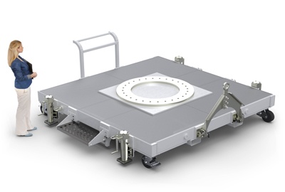
SMP-10000
Mid-Size Satellite Mobile Platform
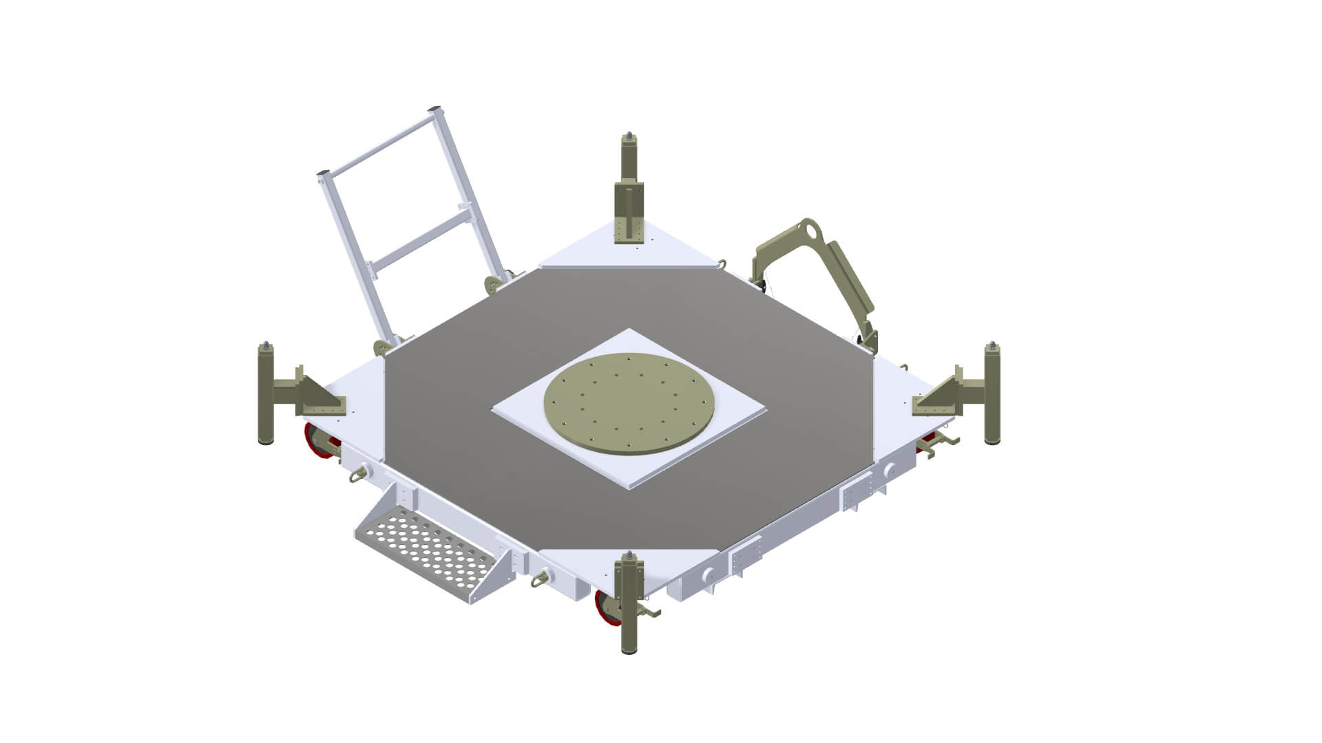
The Mid-Size Satellite Mobile Platform shown below is designed to support mid-sized space vehicles that weigh 10,000 lbs and less and have a CG offset of less than 100” from the mounting interface. For more information, please visit the Mid-Size Satellite Mobile Platforms Options page and SMP-MS CREATING A MODEL NUMBER pdf.


Product Features:
- Safety Factor: 3.
- Rated Load Capacity: 10,000 lbs with CG located at 100” above mounting interface and 5” from the longitudinal axis.
- Operating Temperature: +32° to +104° F (0° to +40° C).
- Payload Interface: Ø48” plate with Ø40” bolt circle.
- Casters: Heavy Duty Ø8” x 3” phenolic or nylon wheels, electro-less nickel-plated finish with brake and swivel lock. (Optional air casters in place of wheeled casters are available)
- Materials: Steel Construction, clean room compatible.
- Finish: CLASS 10K clean room compatible finish – sky white powder coated base frame & push bar, electro-less nickel-plated interface plate, leveling jacks, tow bar and caster bodies (no zinc), stainless steel fasteners and miscellaneous hardware. The casters swivel bearings are lubricated with Krytox GPL207 and the unexposed leveling jack screws are lubricated with Synco Super Lube.
- Optional Tow Bar
- Optional Air Casters
- Optional Push/Pull Bar
- Optional Step
- Optional ESD package (banana plug receptacles & grounding wire)
- Optional Leveling Jacks
- For more about the Satellite Mobile Platform Options click here
All data presented is based on no modifications to the product.
As Flotron is constantly improving products and methods of manufacturing, we reserve the right to modify and/or change design or specifications without notice. Please contact Flotron for verification of critical dimensions and specifications.
For SMP-10000 Series – Creating a Model Number pdf click here.
For clarification of terms or phrases, please see the Holding Fixtures Definitions page.
SFP-747
SFP-645
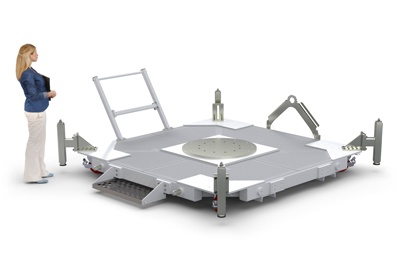
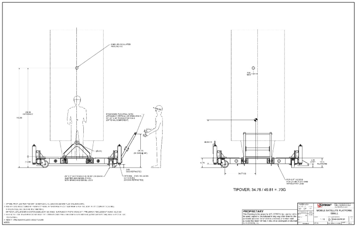
SMP-2000
Small Satellite Mobile Platform Data Sheet
The Small Satellite Mobile Platform shown below is designed to support smaller space vehicles that weigh 2,000 lbs and less and have a CG offset of less than 100” from the mounting interface. For more information, please visit the Small Satellite Mobile Platforms Options page and SMP-SM CREATING A MODEL NUMBER pdf.
Product Features:
- Safety Factor: 3.
- Rated Load Capacity: 2,000 lbs with CG located at 100” above mounting interface and 5” from the longitudinal axis.
- Operating Temperature: +32° to +104° F (0° to +40° C).
- Payload Interface: Ø32” plate with Ø28” hole pattern.
- Casters: Heavy Duty Ø8” x 3” phenolic or nylon wheels, electro-less nickel-plated finish with brake and swivel lock. (Optional air casters in place of wheeled casters are available)
- Materials: Steel Construction, clean room compatible.
- Finish: CLASS 10K clean room compatible finish – sky white powder coated base frame & push bar, electro-less nickel-plated interface plate, leveling jacks, tow bar and caster bodies (no zinc), stainless steel fasteners and miscellaneous hardware. The casters swivel bearings are lubricated with Krytox GPL207 and the unexposed leveling jack screws are lubricated with Synco Super Lube.
- Optional Tow Bar
- Optional Air Casters
- Optional Push/Pull Bar
- Optional Step
- Optional ESD package (banana plug receptacles & grounding wire)
- Optional Leveling Jacks
- For more about the Satellite Mobile Platform Options click here
All data presented is based on no modifications to the product.
As Flotron is constantly improving products and methods of manufacturing, we reserve the right to modify and/or change design or specifications without notice. Please contact Flotron for verification of critical dimensions and specifications.
For SMP-2000 Series – Creating a Model Number pdf click here.
For clarification of terms or phrases, please see the Holding Fixtures Definitions page.
SFP-655
1297
1297 Data Sheet
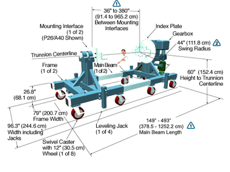
The Model 1297-J2-M-IND15-P26/A40-B080 shown below is typical and representative of the 1297 Models. To specify the correct model number for a specific holding fixture, see the 1200 SERIES OPTIONS pages and 1200 CREATING A MODEL NUMBER pdf.
The maximum distance between mounting interfaces is directly related to the main beam length. Specify the distance between mounting interfaces to be at or slightly larger than the length of the part-to-be-handled. The fixture can be adjusted to accommodate smaller length parts, however, the main beam(s) extending from each end frame may be inconvenient. For more information see the 1200 SERIES OPTIONS page and 12000 SERIES CREATING A MODEL NUMBER pdf.
A smaller than standard swing radius may be recommended for some applications. See the “Technical Section” under “Holding Fixture Safety” on page 3 of 7 concerning “Unexpected Accident Loads” and the chart on page 4 of 7 referring to “Maximum Recommended Swing Radius”
Product Features:
- Safety Factor: 3
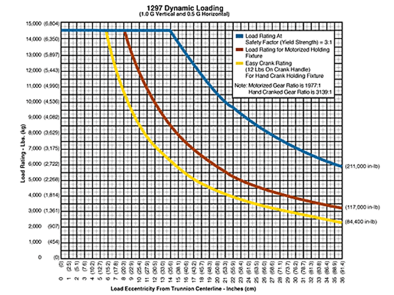
- Rated Load Capacity:
- Dynamic, 0″ to 7.5″ eccentricity: 14,500 lbs. (6,577 kg.)
- Dynamic, 21″ eccentricity: 10,000 lbs. (4,563 kg.)
- Operating Temperature: +32 to +104 °F (0 to +40 °C). Contact factory for special applications with extended operating temperatures.
- Combination Mounting Plate / Angle Interface
- Choice of Main Beam Length
- Main Beam Ball Lock Pins: Reliably prevents End Frames from slipping on Main Beams
- Gearbox: Low backlash, non-backdriving stairstep resistant design with 1977:1 ratio
- Motorized Rotate Drive: The motorized, reversible rotate drive utilizes an inverter duty motor controlled by a programmable variable frequency inverter. Motor speed is reduced to output rotate speed through a multiple reduction, low backlash gearbox system which is designed to eliminate back driving and stair stepping. The maximum output speed is about 0.8 RPM and is controllable down to a minimum speed of about 10% of maximum speed. The motor and controls are designed for continuous operation in an open loop, four quadrant vector control mode. The controls, including circuit breaker, control transformer, braking resister, relays, etc., are enclosed in a NEMA 12 enclosure and the system is UL approved. A back up safety brake is included on the motor to prevent creep during motor off periods. A removable hand crank with safety electrical interlocks is provided for rotating the load in the case of an electrical malfunction.
- Self Aligning Couplings: These zero backlash couplings allow about ½ degree misalignment between load and fixture.
- Gearbox Hub: The zero backlash gearbox hub attaches the gearbox shaft to the index plate and mounting interface. The hub is designed to withstand both torque and overhung loads.
- Casters: 12″ diameter x 5″ wide wheel with polyurethane tread, kingpinless swivel bearing, brake and swivel lock
- Index Plate: Standard with 15° index plate and index stops
- Materials: Steel construction
- Finish: Flotron Blue powder coat with selected parts zinc plated.
- A smaller than standard swing radius may be recommended for some applications. See the “Technical Section” under “Holding Fixture Safety” on page 3 of 7 concerning “Unexpected Accident Loads” and the chart on page 4 of 7 referring to “Maximum Recommended Swing Radius“.
- Optional Motorized Rotate drive with 1975:1 ratio gearbox and variable frequency motor control
- Optional Ground Lug and Drag Chain for use in electrostatically protected areas (EPA’s)
- Optional Main Beam lengths
- Optional Leveling Jacks
- For more about 1200 Series Options click here
All data presented is based on no modifications to the product.
As Flotron is constantly improving products and methods of manufacturing, we reserve the right to modify and/or change design or specifications without notice. Please contact Flotron for verification of critical dimensions and specifications.
For 1200 Series – Creating a Model Number pdf click here.
For clarification of terms or phrases, please see the Holding Fixtures Definitions page.
1279
1279 Data Sheet
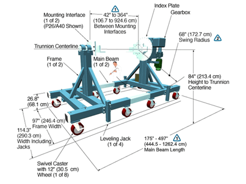
The Model 1279-J2-M-IND15-P26/A40-B080 shown below is typical and representative of the 1279 Models. To specify the correct model number for a specific holding fixture, see the 1200 SERIES OPTIONS pages and 1200 CREATING A MODEL NUMBER pdf.
The maximum distance between mounting interfaces is directly related to the main beam length. Specify the distance between mounting interfaces to be at or slightly larger than the length of the part-to-be-handled. The fixture can be adjusted to accommodate smaller length parts, however, the main beam(s) extending from each end frame may be inconvenient. For more information see the 1200 SERIES OPTIONS page and 12000 SERIES CREATING A MODEL NUMBER pdf.
A smaller than standard swing radius may be recommended for some applications. See the “Technical Section” under “Holding Fixture Safety” on page 3 of 7 concerning “Unexpected Accident Loads” and the chart on page 4 of 7 referring to “Maximum Recommended Swing Radius”
Product Features:
- Safety Factor: 3
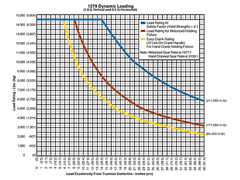
- Rated Load Capacity:
- Dynamic, 0″ to 7.5″ eccentricity: 14,500 lbs. (6,577 kg.)
- Dynamic, 21″ eccentricity: 10,000 lbs. (4,563 kg.)
- Operating Temperature: +32 to +104 °F (0 to +40 °C). Contact factory for special applications with extended operating temperatures.
- Combination Mounting Plate / Angle Interface
- Choice of Main Beam Length
- Main Beam Ball Lock Pins: Reliably prevents End Frames from slipping on Main Beams
- Gearbox: Low backlash, non-backdriving stairstep resistant design with 1977:1 ratio
- Motorized Rotate Drive: The motorized, reversible rotate drive utilizes an inverter duty motor controlled by a programmable variable frequency inverter. Motor speed is reduced to output rotate speed through a multiple reduction, low backlash gearbox system which is designed to eliminate back driving and stair stepping. The maximum output speed is about 0.8 RPM and is controllable down to a minimum speed of about 10% of maximum speed. The motor and controls are designed for continuous operation in an open loop,four quadrant vector control mode. The controls, including circuit breaker, control transformer, braking resister, relays, etc., are enclosed in a NEMA 12 enclosure and the system is UL approved. A back up safety brake is included on the motor to prevent creep during motor off periods. A removable hand crank with safety electrical interlocks is provided for rotating the load in the case of an electrical malfunction.
- Self Aligning Couplings: These zero backlash couplings allow about ½ degree misalignment between load and fixture.
- Gearbox Hub: The zero backlash gearbox hub attaches the gearbox shaft to the index plate and mounting interface. The hub is designed to withstand both torque and overhung loads.
- Casters: 12″ diameter x 5″ wide wheel with polyurethane tread, kingpinless swivel bearing, brake and swivel lock
- Index Plate: Standard with 15° index plate and index stops
- Materials: Steel construction
- Finish: Flotron Blue powder coat with selected parts zinc plated.
- A smaller than standard swing radius may be recommended for some applications. See the “Technical Section” under “Holding Fixture Safety” on page 3 of 7 concerning “Unexpected Accident Loads” and the chart on page 4 of 7 referring to “Maximum Recommended Swing Radius“.
- Optional Motorized Rotate drive with 1975:1 ratio gearbox and variable frequency motor control
- Optional Ground Lug and Drag Chain for use in electrostatically protected areas (EPA’s)
- Optional Main Beam lengths
- Optional Leveling Jacks
- For more about 1200 Series Options click here
All data presented is based on no modifications to the product.
As Flotron is constantly improving products and methods of manufacturing, we reserve the right to modify and/or change design or specifications without notice. Please contact Flotron for verification of critical dimensions and specifications.
For 1200 Series – Creating a Model Number pdf click here
For clarification of terms or phrases, please see the Holding Fixtures Definitions page.