XD739DB-HYD Data Sheet
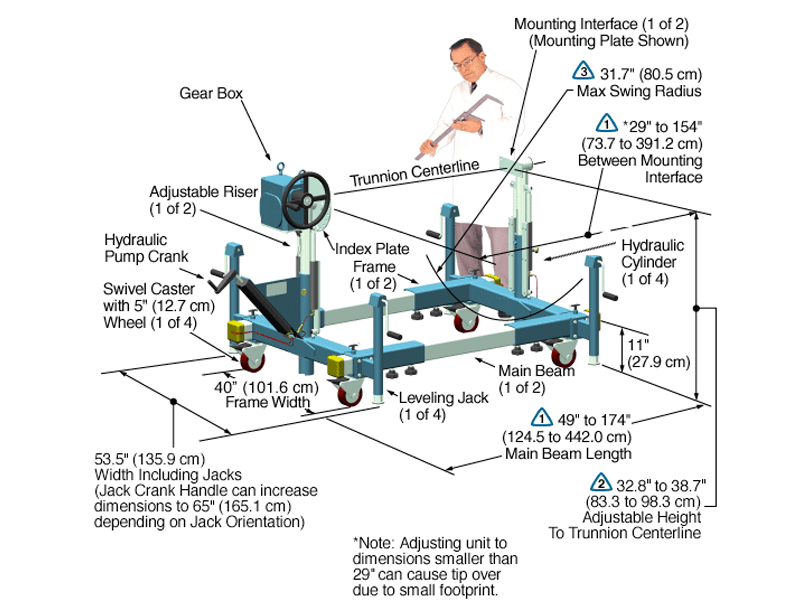
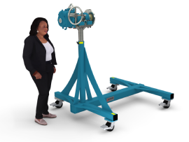
The Model XD739DB-HYD-J2-IND15-P8-B048 shown below is typical and representative of the XD739DB-HYD Models. For more information on specifying a holding fixture see the 700 SERIES OPTIONS page and 700 SERIES CREATING A MODEL NUMBER pdf.
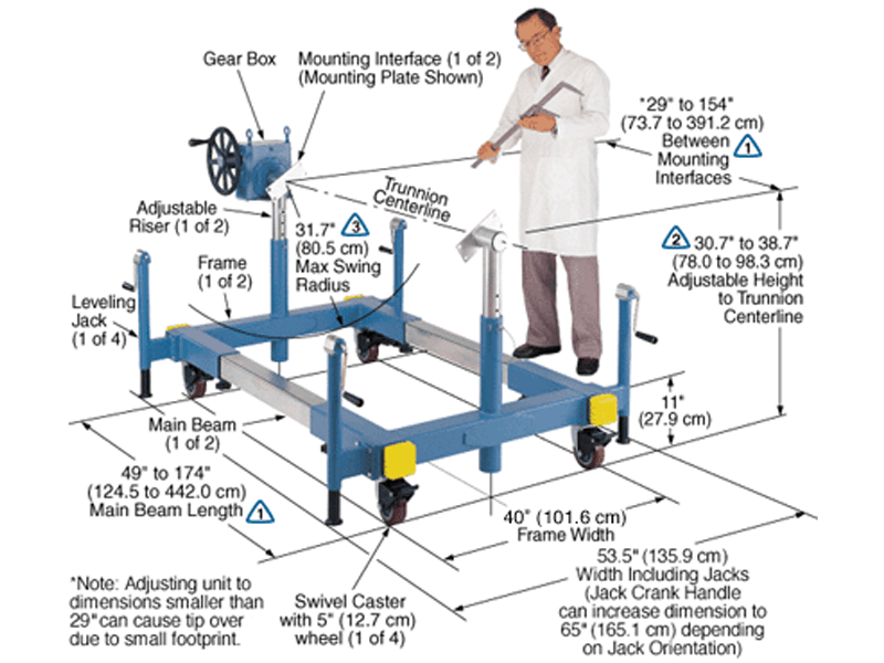
The maximum distance between mounting interfaces is directly related to the main beam length. Specify the distance between mounting interfaces to be at or slightly larger than the length of the part-to-be-handled. The fixture can be adjusted to accommodate smaller length parts, however, the main beam(s) extending from each end frame may be inconvenient. For more information see the
700 SERIES OPTIONS page and
700 SERIES CREATING A MODEL NUMBER pdf.
Addition of the optional SR or DR gearbox decreases the vertical riser adjustment from 12″ to 10″ and increases the minimum trunnion height from 46.7″ to 48.7″.
A smaller than standard swing radius may be recommended for some applications. See the “Technical Section” under “Holding Fixture Safety” on page 3 of 7 concerning “Unexpected Accident Loads” and the chart on page 4 of 7 referring to “Maximum Recommended Swing Radius”
Product Features:
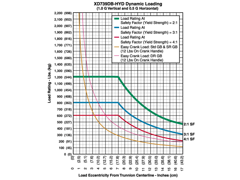
- Safety Factor: 3
- Rated Load Capacity:
- Dynamic, 0″ eccentricity: 800 lbs. (363 kg.)
- Dynamic, 5″ eccentricity: 800 lbs. (363 kg.)
- Note: The hydraulic cylinders are single acting and a minimum load of 150 lbs is recommended to activate the return (compression) stroke and to give good synchronization of the risers.
- Operating Temperature: +32 to +104 °F (0 to +40 °C). Contact factory for special applications with extended operating temperatures.
- Choice of Trunnion Interface/Mount/Clamp Options:
- Angle Interface
- Mounting Plate Interface
- Synchronized Hydraulic Risers
The hydraulic risers can adjust the height of the part-to-be-handled while it is attached to the trunnion interfaces. Turning the pump crank clockwise or counter-clockwise causes the risers to raise or lower in unison.
- Choice of Main Beam Length
- Main Beam Ball Lock Pin: Reliably prevents End Frames from slipping on Main Beam
- Gearbox: 60:1 ratio with 12″ diameter crank
- Casters: 5″ diameter x 2″ wide wheel with polyurethane tread, sealed swivel bearing and Tech-lock brake
- Materials: Steel construction
- Finish: Flotron Blue powder coat with selected parts zinc plated.
- A smaller than standard swing radius may be recommended for some applications. See the “Technical Section” under “Holding Fixture Safety” on page 3 of 7 concerning “Unexpected Accident Loads” and the chart on page 4 of 7 referring to “Maximum Recommended Swing Radius“.
- Optional Main Beam Lengths
- Optional Trunnion Interface/Mount/Clamp
- Optional Index Plate
- Optional Index Stops
- Optional Casters
- Optional Leveling Jacks
- Optional Gearboxes incorporating heavy duty, low backlash and stairstep resistant features
- Optional finishes for clean room compatibility
- Optional Ground Lug and Drag Chain for use in electrostatically protected areas (EPA’s)
- For more about 700 Series Options click here
All data presented is based on no modifications to the product.
As Flotron is constantly improving products and methods of manufacturing, we reserve the right to modify and/or change design or specifications without notice. Please contact Flotron for verification of critical dimensions and specifications.
For 700 Series – Creating a Model Number pdf click here.
For clarification of terms or phrases, please see the Holding Fixtures Definitions page.
XD759-HYD Data Sheet
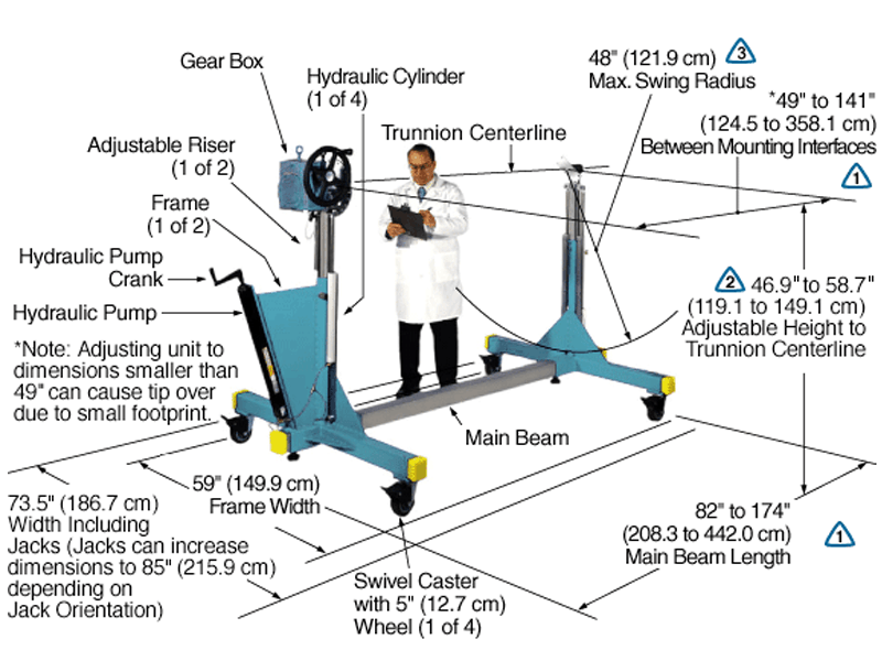
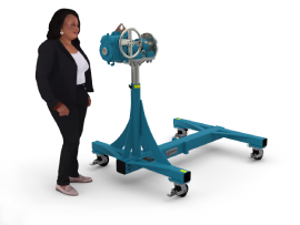
The Model XD759-HYD-IND15-P8-B072 shown below is typical and representative of the XD759-HYD Models. For more information on specifying a holding fixture, see the 700 SERIES OPTIONS page and 700 SERIES CREATING A MODEL NUMBER pdf.
The maximum distance between mounting interfaces is directly related to the main beam length. Specify the distance between mounting interfaces to be at or slightly larger than the length of the part-to-be-handled. The fixture can be adjusted to accommodate smaller length parts, however, the main beam(s) extending from each end frame may be inconvenient. For more information see the
700 SERIES OPTIONS page and
700 SERIES CREATING A MODEL NUMBER pdf.
Addition of the optional SR or DR gearbox decreases the vertical riser adjustment from 12″ to 10″ and increases the minimum trunnion height from 46.7″ to 48.7″.
A smaller than standard swing radius may be recommended for some applications. See the “Technical Section” under “Holding Fixture Safety” on page 3 of 7 concerning “Unexpected Accident Loads” and the chart on page 4 of 7 referring to “Maximum Recommended Swing Radius”
Product Features:
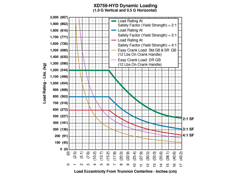
- Safety Factor: 3
- Rated Load Capacity:
- Dynamic, 0″ eccentricity: 800 lbs. (363 kg.)
- Dynamic, 5″ eccentricity: 800 lbs. (363 kg.)
- Note: The hydraulic cylinders are single acting and a minimum load of 150 lbs is recommended to activate the return (compression) stroke and to give good synchronization of the risers.
- Operating Temperature: +32 to +104 °F (0 to +40 °C). Contact factory for special applications with extended operating temperatures.
- Choice of Trunnion Interface/Mount/Clamp Options:
- Angle Interface
- Mounting Plate Interface
- Synchronized Hydraulic Risers
The hydraulic risers can adjust the height of the part-to-be-handled while it is attached to the trunnion interfaces. Turning the pump crank clockwise or counter-clockwise causes the risers to raise or lower in unison.
- Choice of Main Beam Length
- Main Beam Ball Lock Pin: Reliably prevents End Frames from slipping on Main Beam
- Gearbox: 60:1 ratio with 12″ diameter crank
- Casters: 5″ diameter x 2″ wide wheel with polyurethane tread, sealed swivel bearing and Tech-lock brake
- Materials: Steel construction
- Finish: Flotron Blue powder coat with selected parts zinc plated.
- A smaller than standard swing radius may be recommended for some applications. See the “Technical Section” under “Holding Fixture Safety” on page 3 of 7 concerning “Unexpected Accident Loads” and the chart on page 4 of 7 referring to “Maximum Recommended Swing Radius“.
- Optional Main Beam Lengths
- Optional Trunnion Interface/Mount/Clamp
- Optional Index Plate
- Optional Index Stops
- Optional Casters
- Optional Leveling Jacks
- Optional Gearboxes incorporating heavy duty, low backlash and stairstep resistant features
- Optional finishes for clean room compatibility
- Optional Ground Lug and Drag Chain for use in electrostatically protected areas (EPA’s)
- For more about 700 Series Options click here
All data presented is based on no modifications to the product.
As Flotron is constantly improving products and methods of manufacturing, we reserve the right to modify and/or change design or specifications without notice. Please contact Flotron for verification of critical dimensions and specifications.
For 700 Series – Creating a Model Number pdf click here.
For clarification of terms or phrases, please see the Holding Fixtures Definitions page.
XD747DB-HYD Data Sheet
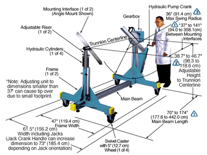
The Model XD747-HYD-IND15-A30-B056 shown below is typical and representative of the XD747-HYD Models. For more information on specifying a holding fixture, see the 700 SERIES OPTIONS page and 700 SERIES CREATING A MODEL NUMBER pdf.
The maximum distance between mounting interfaces is directly related to the main beam length. Specify the distance between mounting interfaces to be at or slightly larger than the length of the part-to-be-handled. The fixture can be adjusted to accommodate smaller length parts, however, the main beam(s) extending from each end frame may be inconvenient. For more information see the
700 SERIES OPTIONS page and
700 SERIES CREATING A MODEL NUMBER pdf.
Addition of the optional SR or DR gearbox decreases the vertical riser adjustment from 8″ to 6″ and increases the minimum trunnion height from 38.7″ to 40.7″.
A smaller than standard swing radius may be recommended for some applications. See the “Technical Section” under “Holding Fixture Safety” on page 3 of 7 concerning “Unexpected Accident Loads” and the chart on page 4 of 7 referring to “Maximum Recommended Swing Radius”
Product Features:
- Safety Factor: 3
- Rated Load Capacity:
- Dynamic, 0″ eccentricity: 800 lbs. (363 kg.)
- Dynamic, 5″ eccentricity: 800 lbs. (363 kg.)
- Note: The hydraulic cylinders are single acting and a minimum load of 150 lbs is recommended to activate the return (compression) stroke and to give good synchronization of the risers.
- Operating Temperature: +32 to +104 °F (0 to +40 °C). Contact factory for special applications with extended operating temperatures.
- Choice of Trunnion Interface/Mount/Clamp Options:
- Angle Interface
- Mounting Plate Interface
- Synchronized Hydraulic Risers
The hydraulic risers can adjust the height of the part-to-be-handled while it is attached to the trunnion interfaces. Turning the pump crank clockwise or counter-clockwise causes the risers to raise or lower in unison.
- Choice of Main Beam Length
- Main Beam Ball Lock Pins: Reliability prevents End Frames from slipping on Main Beams
- Gearbox: 60:1 ratio with 12″ diameter crank
- Casters: 5″ diameter x 2″ wide wheel with polyurethane tread, sealed swivel bearing and Tech-lock brake
- Materials: Steel construction
- Finish: Flotron Blue powder coat with selected parts zinc plated.
- A smaller than standard swing radius may be recommended for some applications. See the “Technical Section” under “Holding Fixture Safety” on page 3 of 7 concerning “Unexpected Accident Loads” and the chart on page 4 of 7 referring to “Maximum Recommended Swing Radius“.
- Optional Main Beam Lengths
- Optional Trunnion Interface/Mount/Clamp
- Optional Index Plate
- Optional Index Stops
- Optional Casters
- Optional Leveling Jacks
- Optional Gearboxes incorporating heavy duty, low backlash and stairstep resistant features
- Optional finishes for clean room compatibility
- Optional Ground Lug and Drag Chain for use in electrostatically protected areas (EPA’s)
- For more about 700 Series Options click here
All data presented is based on no modifications to the product.
As Flotron is constantly improving products and methods of manufacturing, we reserve the right to modify and/or change design or specifications without notice. Please contact Flotron for verification of critical dimensions and specifications.
For 700 Series – Creating a Model Number pdf click here.
For clarification of terms or phrases, please see the Holding Fixtures Definitions page.
XD739-HYD Data Sheet
The Model XD739-HYD-IND15-A30-B054 shown below is typical and representative of the XD739-HYD Models. For more information on specifying a holding fixture, see the 700 SERIES OPTIONS page and 700 SERIES CREATING A MODEL NUMBER pdf.
The maximum distance between mounting interfaces is directly related to the main beam length. Specify the distance between mounting interfaces to be at or slightly larger than the length of the part-to-be-handled. The fixture can be adjusted to accommodate smaller length parts, however, the main beam(s) extending from each end frame may be inconvenient. For more information see the
700 SERIES OPTIONS page and
700 SERIES CREATING A MODEL NUMBER pdf.
Addition of the optional SR or DR gearbox decreases the vertical riser adjustment from 11.8″ to 9.8″ and increases the minimum trunnion height from 46.9″ to 48.9″.
A smaller than standard swing radius may be recommended for some applications. See the “Technical Section” under “Holding Fixture Safety” on page 3 of 7 concerning “Unexpected Accident Loads” and the chart on page 4 of 7 referring to “Maximum Recommended Swing Radius”
Product Features:
- Safety Factor: 3
- Rated Load Capacity:
- Dynamic, 0″ eccentricity: 800 lbs. (363 kg.)
- Dynamic, 5″ eccentricity: 800 lbs. (363 kg.)
- Note: The hydraulic cylinders are single acting and a minimum load of 150 lbs is recommended to activate the return (compression) stroke and to give good synchronization of the risers.
- Operating Temperature: +32 to +104 °F (0 to +40 °C). Contact factory for special applications with extended operating temperatures.
- Choice of Trunnion Interface/Mount/Clamp Options:
- Angle Interface
- Mounting Plate Interface
- Synchronized Hydraulic Risers
The hydraulic risers can adjust the height of the part-to-be-handled while it is attached to the trunnion interfaces. Turning the pump crank clockwise or counter-clockwise causes the risers to raise or lower in unison.
- Choice of Main Beam Length
- Main Beam Ball Lock Pin: Reliably prevents End Frames from slipping on Main Beam
- Gearbox: 60:1 ratio with 12″ diameter crank
- Casters: 5″ diameter x 2″ wide wheel with polyurethane tread, sealed swivel bearing and Tech-lock brake
- Materials: Steel construction
- Finish: Flotron Blue powder coat with selected parts zinc plated.
- A smaller than standard swing radius may be recommended for some applications. See the “Technical Section” under “Holding Fixture Safety” on page 3 of 7 concerning “Unexpected Accident Loads” and the chart on page 4 of 7 referring to “Maximum Recommended Swing Radius”
- Optional Main Beam Lengths
- Optional Trunnion Interface/Mount/Clamp
- Optional Index Plate
- Optional Index Stops
- Optional Casters
- Optional Leveling Jacks
- Optional Gearboxes incorporating heavy duty, low backlash and stairstep resistant features
- Optional finishes for clean room compatibility
- Optional Ground Lug and Drag Chain for use in electrostatically protected areas (EPA’s)
- For more about 700 Series Options click here
All data presented is based on no modifications to the product.
As Flotron is constantly improving products and methods of manufacturing, we reserve the right to modify and/or change design or specifications without notice. Please contact Flotron for verification of critical dimensions and specifications.
For 700 Series – Creating a Model Number pdf click here.
For clarification of terms or phrases, please see the Holding Fixtures Definitions page.
XD759DB Data Sheet
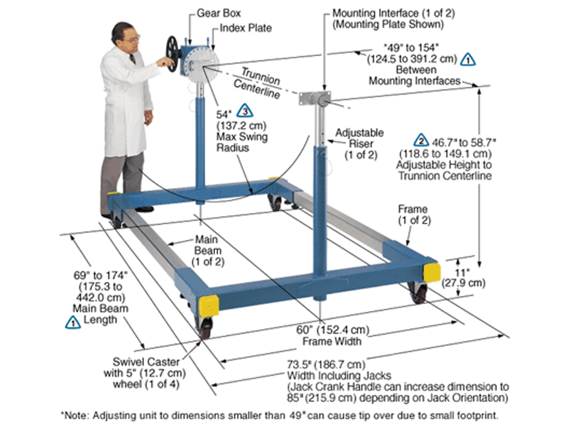
The Model XD759DB-J0-IND15-P8-B078 shown below is typical and representative of the XD759DB Models. For more information on specifying a holding fixture, see the 700 SERIES OPTIONS page and 700 SERIES CREATING A MODEL NUMBER pdf.
The maximum distance between mounting interfaces is directly related to the main beam length. Specify the distance between mounting interfaces to be at or slightly larger than the length of the part-to-be-handled. The fixture can be adjusted to accommodate smaller length parts, however, the main beam(s) extending from each end frame may be inconvenient. For more information see the
700 SERIES OPTIONS page and
700 SERIES CREATING A MODEL NUMBER pdf.
Addition of the optional SR or DR gearbox decreases the vertical riser adjustment from 10″ to 8″ and increases the minimum trunnion height from 36.7″ to 38.7″.
A smaller than standard swing radius may be recommended for some applications. See the “Technical Section” under “Holding Fixture Safety” on page 3 of 7 concerning “Unexpected Accident Loads” and the chart on page 4 of 7 referring to “Maximum Recommended Swing Radius”
Product Features:
- Safety Factor: 3
- Rated Load Capacity:
- Dynamic, 0″ eccentricity: 1,230 lbs. (558 kg.)
- Dynamic, 5″ eccentricity: 960 lbs. (435 kg.)
- Operating Temperature: +32 to +104 °F (0 to +40 °C). Contact factory for special applications with extended operating temperatures.
- Choice of Trunnion Interface/Mount/Clamp Options:
- Angle Interface
- Mounting Plate Interface
- Choice of Main Beam Length
- Main Beam Ball Lock Pins: Reliability prevents End Frames from slipping on Main Beams
- Gearbox: 60:1 ratio with 12″ diameter crank
- Casters: 5″ diameter x 2″ wide wheel with polyurethane tread, sealed swivel bearing and Tech-lock brake
- Materials: Steel construction
- Finish: Flotron Blue powder coat with selected parts zinc plated.
- A smaller than standard swing radius may be recommended for some applications. See the “Technical Section” under “Holding Fixture Safety” on page 3 of 7 concerning “Unexpected Accident Loads” and the chart on page 4 of 7 referring to “Maximum Recommended Swing Radius”
- Optional Main Beam Lengths
- Optional Trunnion Interface/Mount/Clamp
- Optional Index Plate
- Optional Index Stops
- Optional Casters
- Optional Leveling Jacks
- Optional Gearboxes incorporating heavy duty, low backlash and stairstep resistant features
- Optional finishes for clean room compatibility
- Optional Ground Lug and Drag Chain for use in electrostatically protected areas (EPA’s)
- For more about 700 Series Options click here
All data presented is based on no modifications to the product.
As Flotron is constantly improving products and methods of manufacturing, we reserve the right to modify and/or change design or specifications without notice. Please contact Flotron for verification of critical dimensions and specifications.
For 700 Series – Creating a Model Number pdf click here.
For clarification of terms or phrases, please see the Holding Fixtures Definitions page.
CRF 60 Data Sheet
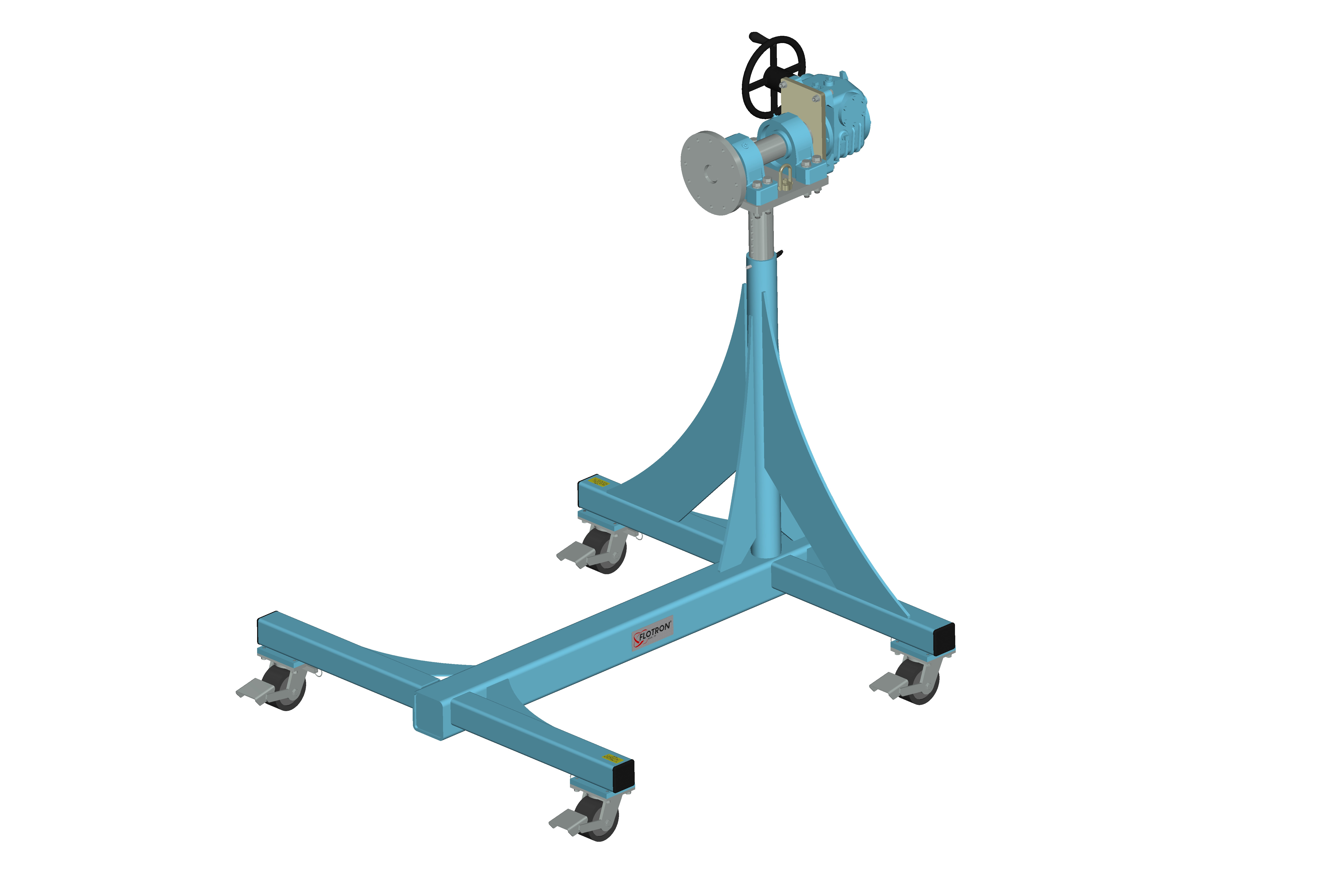
The Model CRF-60‐P12‐C6 shown below is typical and representative of the CRF 60 Models. For more information on specifying a cantilevered rotation fixture, see the CANTILEVERED ROTATION FIXTURE page and CANTILEVERED ROTATION FIXTURE CREATING A MODEL NUMBER pdf.
Product Features:
- Safety Factors: 3 for Yield & 5 for Ultimate
- Rated Load Capacity: 1,000 lbs. with CG located at 30” from interface plate and 2” from primary axis rotation centerline.
- Operating Temperature: +32 to +104 °F (0 to +40 °C). Contact factory for special applications with extended operating temperatures.
- Payload Interface: Ø12” Circular Interface Plate with 12X through holes for 1/2” fasteners on Ø10” bolt circle.
- Gearbox: 60:1ratio with 12” diameter crank.
- Casters: Heavy duty 6″ diameter x 3″ wide phenolic tread, sealed bearings, swivel lock, brake, and steering bar receptacles. (Ø12” diameter optional)
- Materials: Steel construction.
- Finish: Flotron Blue powder coat with selected parts zinc plated.
- Optional Casters.
- Optional Lubricants.
- Optional Tow Bar.
- Optional finishes for clean room compatibility.
- Optional Ground Lug and Drag Chain for use in electrostatically protected areas (EPA’s).
- Optional Standard Proof Load Test
- For more about Cantilevered Rotation Fixture Options click here.
All data presented is based on no modifications to the product.
As Flotron is constantly improving products and methods of manufacturing, we reserve the right to modify and/or change design or specifications without notice. Please contact Flotron for verification of critical dimensions and specifications.
For Cantilevered Rotation Fixtures – Creating a Model Number pdf click here.
For clarification of terms or phrases, please see the Holding Fixtures Definitions page.
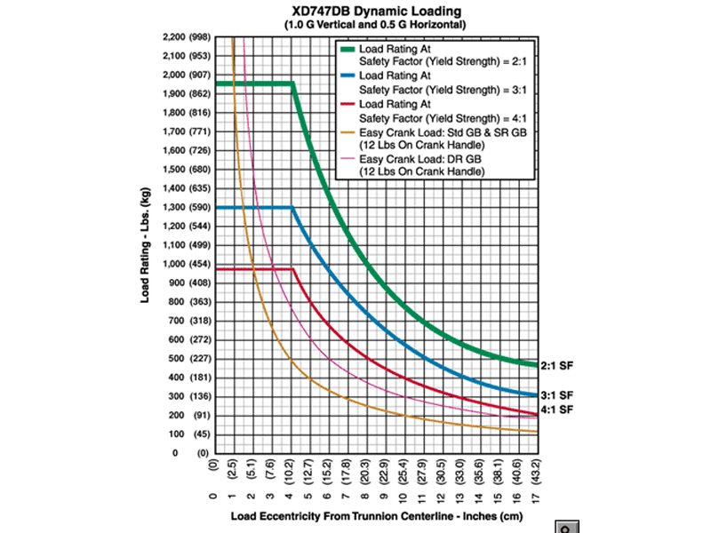
XD747DB Data Sheet
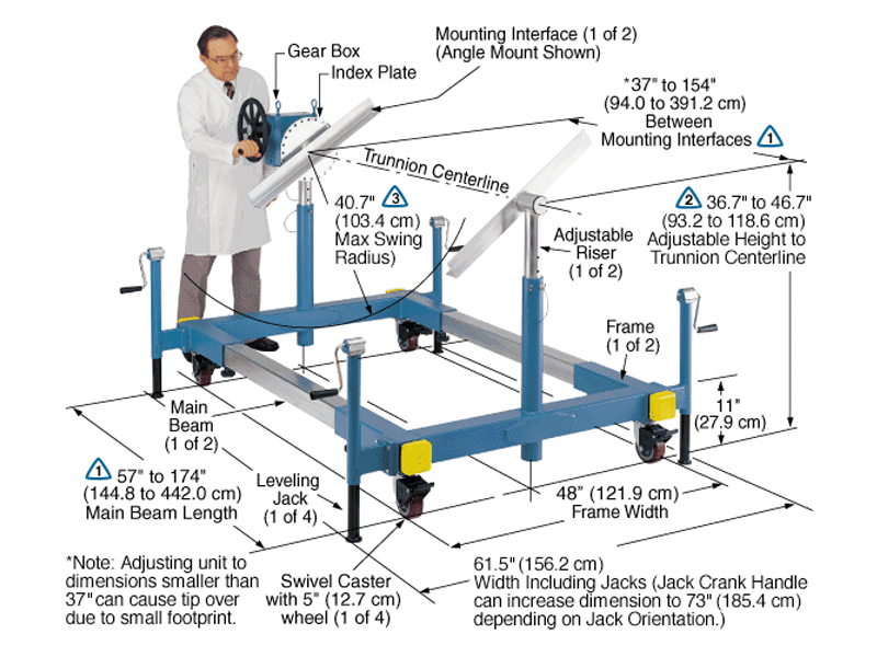
The Model XD747DB-J2-IND15-A30-B060 shown below is typical and representative of the XD747DB Models. For more information on specifying a holding fixture, see the 700 SERIES OPTIONS page and 700 SERIES CREATING A MODEL NUMBER pdf.
The maximum distance between mounting interfaces is directly related to the main beam length. Specify the distance between mounting interfaces to be at or slightly larger than the length of the part-to-be-handled. The fixture can be adjusted to accommodate smaller length parts, however, the main beam(s) extending from each end frame may be inconvenient. For more information see the
700 SERIES OPTIONS page and
700 SERIES CREATING A MODEL NUMBER pdf.
Addition of the optional SR or DR gearbox decreases the vertical riser adjustment from 6″ to 4″ and increases the minimum trunnion height from 38.7″ to 40.7″.
A smaller than standard swing radius may be recommended for some applications. See the “Technical Section” under “Holding Fixture Safety” on page 3 of 7 concerning “Unexpected Accident Loads” and the chart on page 4 of 7 referring to “Maximum Recommended Swing Radius”
Product Features:
- Safety Factor: 3
- Rated Load Capacity:
- Dynamic, 0″ eccentricity: 1,300 lbs. (590 kg.)
- Dynamic, 5″ eccentricity: 1,080 lbs. (490 kg.)
- Operating Temperature: +32 to +104 °F (0 to +40 °C). Contact factory for special applications with extended operating temperatures.
- Choice of Trunnion Interface/Mount/Clamp Options:
- Angle Interface
- Mounting Plate Interface
- Choice of Main Beam Length
- Main Beam Ball Lock Pins: Reliably prevents End Frames from slipping on Main Beams
- Gearbox: 60:1 ratio with 12″ diameter crank
- Casters: 5″ diameter x 2″ wide wheel with polyurethane tread, sealed swivel bearing and Tech-lock brake
- Materials: Steel construction
- Finish: Flotron Blue powder coat with selected parts zinc plated.
- A smaller than standard swing radius may be recommended for some applications. See the “Technical Section” under “Holding Fixture Safety” on page 3 of 7 concerning “Unexpected Accident Loads” and the chart on page 4 of 7 referring to “Maximum Recommended Swing Radius”
- Optional Main Beam Lengths
- Optional Trunnion Interface/Mount/Clamp
- Optional Index Plate
- Optional Index Stops
- Optional Casters
- Optional Leveling Jacks
- Optional Gearboxes incorporating heavy duty, low backlash and stairstep resistant features
- Optional finishes for clean room compatibility
- Optional Ground Lug and Drag Chain for use in electrostatically protected areas (EPA’s)
- For more about 700 Series Options click here
All data presented is based on no modifications to the product.
As Flotron is constantly improving products and methods of manufacturing, we reserve the right to modify and/or change design or specifications without notice. Please contact Flotron for verification of critical dimensions and specifications.
For 700 Series – Creating a Model Number pdf click here.
For clarification of terms or phrases, please see the Holding Fixtures Definitions page.
CRF 48 Data Sheet
The Model CRF-48‐P12‐C6 shown below is typical and representative of the CTL48 Models. For more information on specifying a cantilevered rotation fixture, see the CANTILEVERED ROTATION FIXTURE page and CANTILEVERED ROTATION FIXTURE CREATING A MODEL NUMBER pdf.
Product Features:
- Safety Factors: 3 for Yield & 5 for Ultimate
- Rated Load Capacity: 1,000 lbs. with CG located at 30” from interface plate and 2” from primary axis rotation centerline.
- Operating Temperature: +32 to +104 °F (0 to +40 °C). Contact factory for special applications with extended operating temperatures.
- Payload Interface: Ø12” Circular Interface Plate with 12X through holes for 1/2” fasteners on Ø10” bolt circle.
- Gearbox: 60:1ratio with 12” diameter crank.
- Casters: Heavy duty 6″ diameter x 3″ wide phenolic tread, sealed bearings, swivel lock, brake, and steering bar receptacles. (Ø12” diameter optional)
- Materials: Steel construction.
- Finish: Flotron Blue powder coat with selected parts zinc plated.
- Optional Casters.
- Optional Lubricants.
- Optional Tow Bar.
- Optional finishes for clean room compatibility.
- Optional Ground Lug and Drag Chain for use in electrostatically protected areas (EPA’s).
- Optional Standard Proof Load Test
- For more about Cantilevered Rotation Fixture Options click here.
All data presented is based on no modifications to the product.
As Flotron is constantly improving products and methods of manufacturing, we reserve the right to modify and/or change design or specifications without notice. Please contact Flotron for verification of critical dimensions and specifications.
For Cantilevered Rotation Fixtures – Creating a Model Number pdf click here.
For clarification of terms or phrases, please see the Holding Fixtures Definitions page.
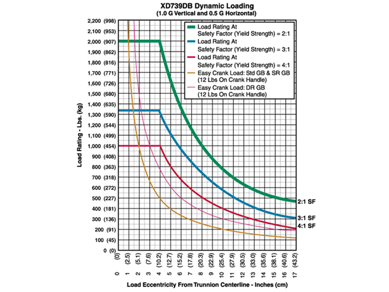
XD739DB Data Sheet
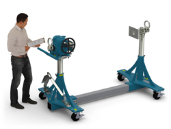
The Model XD739DB-J3-P8-B052 shown below is typical and representative of the XD739DB Models. For more information on specifying a holding fixture, see the 700 SERIES OPTIONS page and 700 SERIES CREATING A MODEL NUMBER pdf.
The maximum distance between mounting interfaces is directly related to the main beam length. Specify the distance between mounting interfaces to be at or slightly larger than the length of the part-to-be-handled. The fixture can be adjusted to accommodate smaller length parts, however, the main beam(s) extending from each end frame may be inconvenient. For more information see the
700 SERIES OPTIONS page and
700 SERIES CREATING A MODEL NUMBER pdf.
Addition of the optional SR or DR gearbox decreases the vertical riser adjustment from 5.9″ to 3.9″ and increases the minimum trunnion height from 32.8″ to 34.8″.
A smaller than standard swing radius may be recommended for some applications. See the “Technical Section” under “Holding Fixture Safety” on page 3 of 7 concerning “Unexpected Accident Loads” and the chart on page 4 of 7 referring to “Maximum Recommended Swing Radius”
Product Features:
- Safety Factor: 3
- Rated Load Capacity:
- Dynamic, 0″ eccentricity: 1,330 lbs. (603 kg.)
- Dynamic, 5″ eccentricity: 1,080 lbs. (490 kg.)
- Dynamic, 5″ eccentricity: 920 lbs. (417 kg.)
- Operating Temperature: +32 to +104 °F (0 to +40 °C). Contact factory for special applications with extended operating temperatures.
- Choice of Trunnion Interface/Mount/Clamp Options:
- Angle Interface
- Mounting Plate Interface
- Choice of Main Beam Length
- Main Beam Ball Lock Pins: Reliably prevents End Frames from slipping on Main Beams
- Gearbox: 60:1 ratio with 12″ diameter crank
- Casters: 5″ diameter x 2″ wide wheel with polyurethane tread, sealed swivel bearing and Tech-lock brake
- Materials: Steel construction
- Finish: Flotron Blue powder coat with selected parts zinc plated.
- A smaller than standard swing radius may be recommended for some applications. See the “Technical Section” under “Holding Fixture Safety” on page 3 of 7 concerning “Unexpected Accident Loads” and the chart on page 4 of 7 referring to “Maximum Recommended Swing Radius”
- Optional Main Beam Lengths
- Optional Trunnion Interface/Mount/Clamp
- Optional Index Plate
- Optional Index Stops
- Optional Casters
- Optional Leveling Jacks
- Optional gearboxes incorporating heavy duty, low backlash and stairstep resistant features
- Optional finishes for clean room compatibility
- Optional ground lug and Drag for use in electrostatically protected areas (EPA’s)
- For more about 700 Series Options click here
All data presented is based on no modifications to the product.
As Flotron is constantly improving products and methods of manufacturing, we reserve the right to modify and/or change design or specifications without notice. Please contact Flotron for verification of critical dimensions and specifications.
For 700 Series – Creating a Model Number pdf click here.
For clarification of terms or phrases, please see the Holding Fixtures Definitions page.