CTL48 Data Sheet
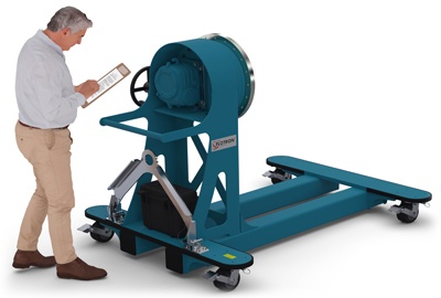
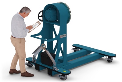
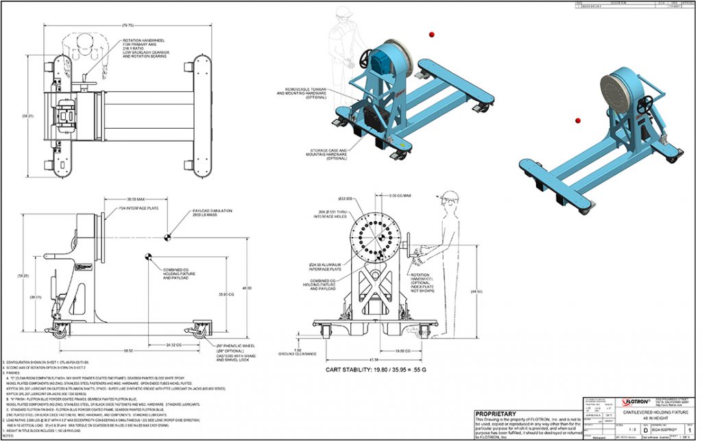
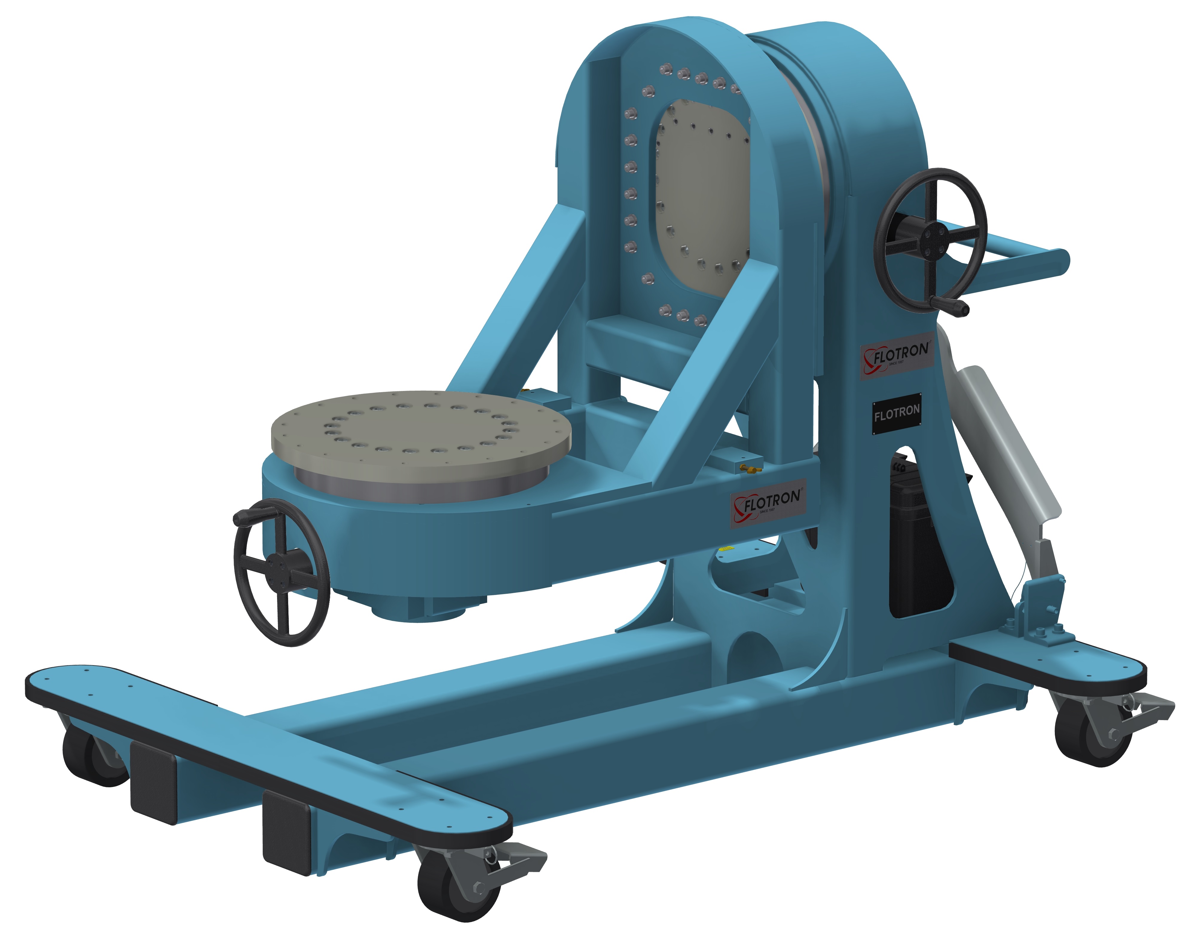
The Model CTL48‐P24‐C6‐T1‐BX shown below is typical and representative of the CTL48 Models. For more information on specifying a cantilevered rotation fixture, see the SMALL SATELLITE FIXTURE OPTIONS page and SMALL SATELLITE FIXTURE CREATING A MODEL NUMBER pdf.
Product Features:
- Safety Factor: 3
- Rated Load Capacity: 2,600 lbs with CG located at 30” from interface plate and 3.0” from rotation centerline.
- Operating Temperature: +32 to +104 °F (0 to +40 °C). Contact factory for special applications with extended operating temperatures.
- Trunnion Interface/Mount/Clamp Options: Ø24” Circular Interface Plate with 20X through holes for ½” fasteners on Ø22” bolt circle.
- Gearbox: 60:1 ratio with 12″ diameter crank.
- Casters: Heavy duty 6″ diameter x 3″ wide wheel with phenolic tread, sealed swivel bearing. Tech‐lock brake and swivel locks.
- Materials: Steel construction.
- Finish: Flotron Blue powder coat with selected parts zinc plated.
- Optional Index Plate.
- Optional Casters.
- Optional Tow Bar.
- Optional Tool Box.
- Optional finishes for clean room compatibility.
- Optional Ground Lug and Drag Chain for use in electrostatically protected areas (EPA’s).
- For more about Small Satellite Fixture Options click here.
All data presented is based on no modifications to the product.
As Flotron is constantly improving products and methods of manufacturing, we reserve the right to modify and/or change design or specifications without notice. Please contact Flotron for verification of critical dimensions and specifications.
For Small Satellite Fixture – Creating a Model Number pdf click here.
For clarification of terms or phrases, please see the Holding Fixtures Definitions page.
CTL60 Data Sheet
The Model CTL60‐P24‐C6‐T1‐BX shown below is typical and representative of the CTL60 Models. For more information on specifying a cantilevered rotation fixture, see the SMALL SATELLITE FIXTURE OPTIONS page and SMALL SATELLITE FIXTURE CREATING A MODEL NUMBER pdf.
Product Features:
- Safety Factor: 3
- Rated Load Capacity: 2,200 lbs with CG located at 30” from interface plate and 3.6” from rotation centerline.
- Operating Temperature: +32 to +104 °F (0 to +40 °C). Contact factory for special applications with extended operating temperatures.
- Trunnion Interface/Mount/Clamp Options: Ø24” Circular Interface Plate with 20X through holes for ½” fasteners on Ø22” bolt circle.
- Gearbox: 60:1 ratio with 12″ diameter crank.
- Casters: Heavy duty 6″ diameter x 3″ wide wheel with phenolic tread, sealed swivel bearing. Tech‐lock brake and swivel locks.
- Materials: Steel construction.
- Finish: Flotron Blue powder coat with selected parts zinc plated.
- Optional Index Plate.
- Optional Casters.
- Optional Tow Bar.
- Optional Tool Box.
- Optional finishes for clean room compatibility.
- Optional Ground Lug and Drag Chain for use in electrostatically protected areas (EPA’s).
- For more about Small Satellite Fixture Options click here.
All data presented is based on no modifications to the product.
As Flotron is constantly improving products and methods of manufacturing, we reserve the right to modify and/or change design or specifications without notice. Please contact Flotron for verification of critical dimensions and specifications.
For Small Satellite Fixture – Creating a Model Number pdf click here.
For clarification of terms or phrases, please see the Holding Fixtures Definitions page.
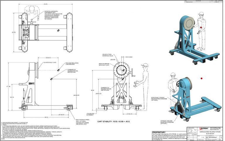
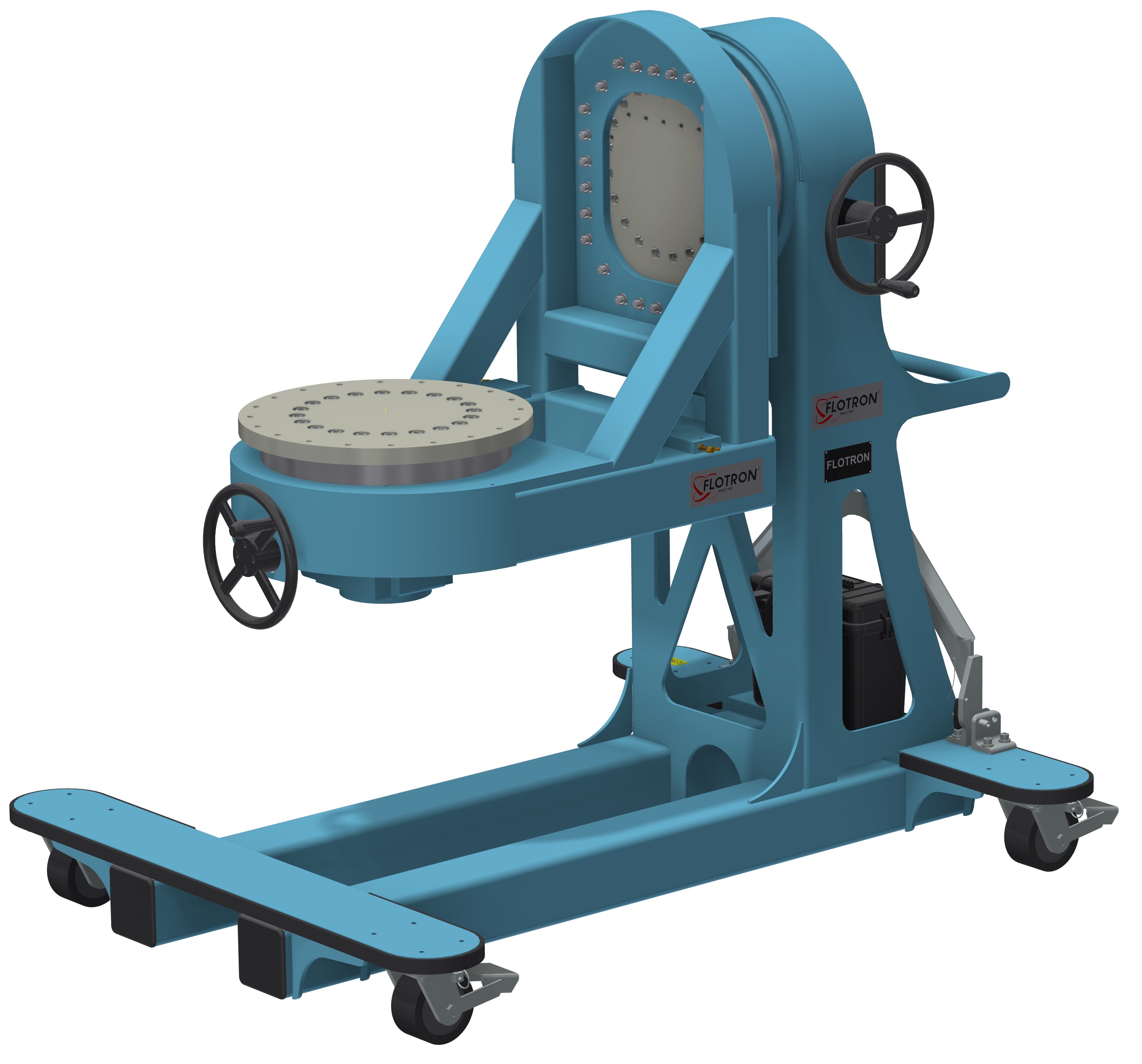
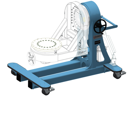
HD664 Data Sheet
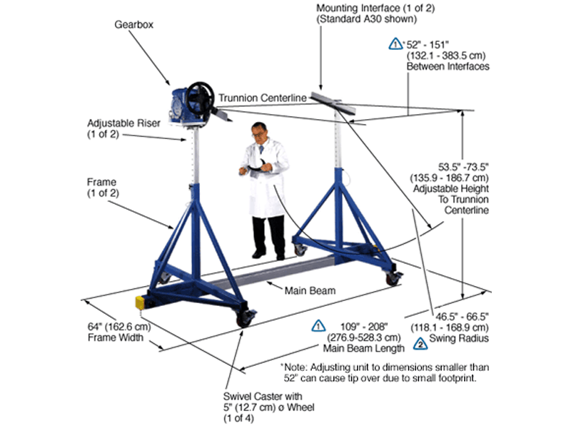
The Model HD664-SR-IND15-A30-B063-C1 shown below is typical and representative of the HD664 Models. For more information on specifying a holding fixture, see the 600 SERIES OPTIONS page and 600 SERIES CREATING A MODEL NUMBER pdf.
The maximum distance between mounting interfaces is directly related to the main beam length. Specify the distance between mounting interfaces to be at or slightly larger than the length of the part-to-be-handled. The fixture can be adjusted to accommodate smaller length parts, however, the main beam(s) extending from each end frame may be inconvenient. For more information see the
600 SERIES OPTIONS page and
600 SERIES CREATING A MODEL NUMBER pdf.
A smaller than standard swing radius may be recommended for some applications. See the “Technical Section” under “Holding Fixture Safety” on page 3 of 7 concerning “Unexpected Accident Loads” and the chart on page 4 of 7 referring to “Maximum Recommended Swing Radius”
* Note: Adjusting unit to dimensions smaller than 52″ can cause tip over due to small footprint.
Product Features:
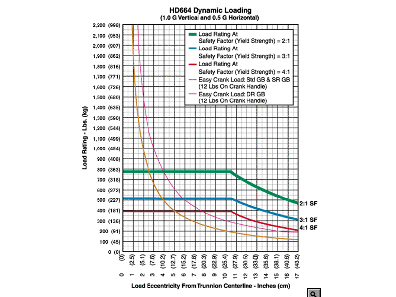
- Safety Factor: 3
- Rated Load Capacity:
- Dynamic, 0″ eccentricity: 520 lbs. (236 kg.)
- Dynamic, 5″ eccentricity: 520 lbs. (236 kg.)
- Operating Temperature: +32 to +104 °F (0 to +40 °C). Contact factory for special applications with extended operating temperatures.
- Choice of Trunnion Interface/Mount/Clamp Options:
- Angle Interface
- Mounting Plate Interface
- Choice of Main Beam Length
- Main Beam Ball Lock Pins: Reliably prevents End Frames from slipping on Main Beam
- Gearbox: SR low backlash gearbox with 60:1 ratio & 12″ diameter crank
- Casters: 5″ diameter x 2″ wide wheel with polyurethane tread, sealed swivel bearing and Tech-lock brake
- Materials: Steel construction
- Finish: Flotron Blue powder coat with selected parts zinc plated.
- A smaller than standard swing radius may be recommended for some applications. See the “Technical Section” under “Holding Fixture Safety” on page 3 of 7 concerning “Unexpected Accident Loads” and the chart on page 4 of 7 referring to “Maximum Recommended Swing Radius”
- Optional Main Beam Lengths
- Optional Trunnion Interface/Mount/Clamp
- Optional Index Plate
- Optional Index Stops
- Optional Casters
- Optional DR low backlash, stairstep resistant Gearbox
- Optional Split Pillow Block Trunnion Bearings
- Optional finishes for clean room compatibility
- Optional Ground Lug and Drag Chain for use in electrostatically protected areas (EPA’s)
- For more about 600 Series Options click here
All data presented is based on no modifications to the product.
As Flotron is constantly improving products and methods of manufacturing, we reserve the right to modify and/or change design or specifications without notice. Please contact Flotron for verification of critical dimensions and specifications.
For 600 Series – Creating a Model Number pdf click here
For clarification of terms or phrases, please see the Holding Fixtures Definitions page.
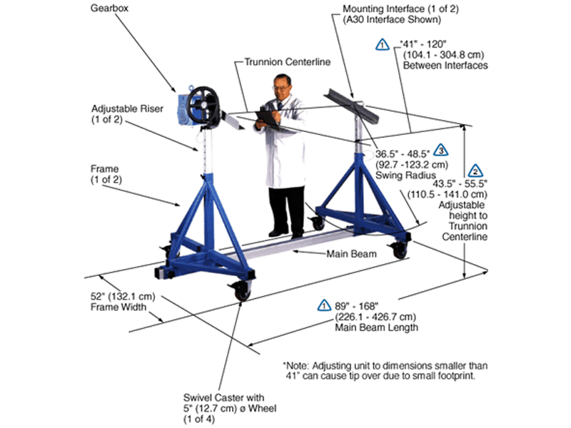
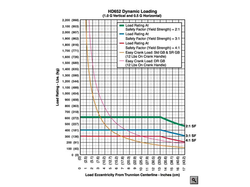
HD652 Data Sheet
The Model HD652-IND15-A30-B057 shown below is typical and representative of the HD652 Models. For more information on specifying a holding fixture, see the 600 SERIES OPTIONS page and 600 SERIES CREATING A MODEL NUMBER pdf.
The maximum distance between mounting interfaces is directly related to the main beam length. Specify the distance between mounting interfaces to be at or slightly larger than the length of the part-to-be-handled. The fixture can be adjusted to accommodate smaller length parts, however, the main beam(s) extending from each end frame may be inconvenient. For more information see the
600 SERIES OPTIONS page and
600 SERIES CREATING A MODEL NUMBER pdf.
Addition of the optional SR or DR gearbox decreases the vertical riser adjustment from 12″ to 10″ and increases the minimum trunnion height from 43.5″ and 45.5″.
A smaller than standard swing radius may be recommended for some applications. See the “Technical Section” under “Holding Fixture Safety” on page 3 of 7 concerning “Unexpected Accident Loads” and the chart on page 4 of 7 referring to “Maximum Recommended Swing Radius”* Note: Adjusting unit to dimensions smaller than 41” can cause tip over due to small footprint.
Product Features:
- Safety Factor: 3
- Rated Load Capacity:
- Dynamic, 0″ eccentricity: 400 lbs. (181 kg.)
- Dynamic, 5″ eccentricity: 400 lbs. (181 kg.)
- Operating Temperature: +32 to +104 °F (0 to +40 °C). Contact factory for special applications with extended operating temperatures.
- Choice of Trunnion Interface/Mount/Clamp Options:
- Angle Interface
- Mounting Plate Interface
- Main Beam Ball Lock Pins: Reliably prevents End Frames from slipping on Main Beam
- Gearbox: 60:1 ratio with 12″ diameter crank
- Casters: 5″ diameter x 2″ wide wheel with polyurethane tread, sealed swivel bearing and Tech-lock brake
- Materials: Steel construction
- Finish: Flotron Blue powder coat with selected parts zinc plated.
- A smaller than standard swing radius may be recommended for some applications. See the “Technical Section” under “Holding Fixture Safety” on page 3 of 7 concerning “Unexpected Accident Loads” and the chart on page 4 of 7 referring to “Maximum Recommended Swing Radius”
- Optional Main Beam Lengths
- Optional Trunnion Interface/Mount/Clamp
- Optional Index Plate
- Optional Index Stops
- Optional Casters
- Optional Gearboxes incorporating heavy duty, low backlash and stairstep resistant features
- Optional Split Pillow Block Trunnion Bearings
- Optional finishes for clean room compatibility
- Optional Ground Lug and Drag Chain for use in electrostatically protected areas (EPA’s)
- For more about 600 Series Options click here
All data presented is based on no modifications to the product.
As Flotron is constantly improving products and methods of manufacturing, we reserve the right to modify and/or change design or specifications without notice. Please contact Flotron for verification of critical dimensions and specifications.
For 600 Series – Creating a Model Number pdf click here
For clarification of terms or phrases, please see the Holding Fixtures Definitions page.
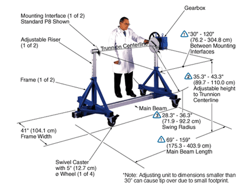
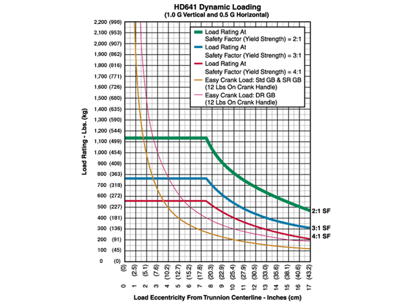
HD641 Data Sheet
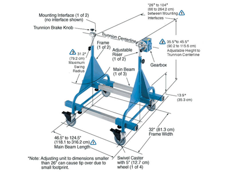
The Model HD641-IND15-P8-B045 shown below is typical and representative of the HD641 Models. For more information on specifying a holding fixture, see the 600 SERIES OPTIONS page and 600 SERIES CREATING A MODEL NUMBER pdf.
The maximum distance between mounting interfaces is directly related to the main beam length. Specify the distance between mounting interfaces to be at or slightly larger than the length of the part-to-be-handled. The fixture can be adjusted to accommodate smaller length parts, however, the main beam(s) extending from each end frame may be inconvenient. For more information see the
600 SERIES OPTIONS page and
600 SERIES CREATING A MODEL NUMBER pdf.
Addition of an optional SR or DR gearbox decreases the vertical riser adjustment from 8″ to 6″ and increases the minimum trunnion height from 35.3″ to 37.3″.
A smaller than standard swing radius may be recommended for some applications. See the “Technical Section” under “Holding Fixture Safety” on page 3 of 7 concerning “Unexpected Accident Loads” and the chart on page 4 of 7 referring to “Maximum Recommended Swing Radius”
* Note: Adjusting unit to dimensions smaller than 30″ can cause tip over due to small footprint.
Product Features:
- Safety Factor: 3
- Rated Load Capacity:
- Dynamic, 0″ eccentricity: 760 lbs. (345 kg.)
- Dynamic, 5″ eccentricity: 760 lbs. (345 kg.)
- Operating Temperature: +32 to +104 °F (0 to +40 °C). Contact factory for special applications with extended operating temperatures.
- Choice of Trunnion Interface/Mount/Clamp Options:
- Angle Interface
- Mounting Plate Interface
- Choice of Main Beam Length
- Main Beam Ball Lock Pins: Reliably prevents End Frames from slipping on Main Beam
- Gearbox: 60:1 ratio with 12″ diameter crank
- Casters: 5″ diameter x 2″ wide wheel with polyurethane tread, sealed swivel bearing and Tech-lock brake
- Materials: Steel construction
- Finish: Flotron Blue powder coat with selected parts zinc plated.
- A smaller than standard swing radius may be recommended for some applications. See the “Technical Section” under “Holding Fixture Safety” on page 3 of 7 concerning “Unexpected Accident Loads” and the chart on page 4 of 7 referring to “Maximum Recommended Swing Radius”
- Optional Main Beam Lengths
- Optional Trunnion Interface/Mount/Clamp
- Optional Index Plate
- Optional Index Stops
- Optional Gearboxes incorporating heavy duty, low backlash and stairstep resistant features
- Optional Split Pillow Block Trunnion Bearings
- Optional finishes for clean room compatibility
- Optional Ground Lug and Drag Chain for use in electrostatically protected areas (EPA’s)
- For more about 600 Series Options click here
All data presented is based on no modifications to the product.
As Flotron is constantly improving products and methods of manufacturing, we reserve the right to modify and/or change design or specifications without notice. Please contact Flotron for verification of critical dimensions and specifications.
For 600 Series – Creating a Model Number pdf click here
For clarification of terms or phrases, please see the Holding Fixtures Definitions page.
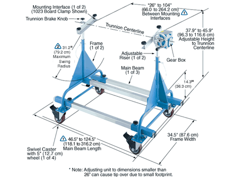
HD525 Data Sheet
The Model HD525-1023-B048 shown below is typical and representative of the HD525 Models. For more information on specifying a holding fixture, see the 500 SERIES OPTIONS page and 500 SERIES CREATING A MODEL NUMBER pdf.
The maximum distance between mounting interfaces is directly related to the main beam length. Specify the distance between mounting interfaces to be at or slightly larger than the length of the part-to-be-handled. The fixture can be adjusted to accommodate smaller length parts, however, the main beam(s) extending from each end frame may be inconvenient. For more information see the
500 SERIES OPTIONS page and
500 SERIES CREATING A MODEL NUMBER pdf.
A smaller than standard swing radius may be recommended for some applications. See the “Technical Section” under “Holding Fixture Safety” on page 3 of 7 concerning “Unexpected Accident Loads” and the chart on page 4 of 7 referring to “Maximum Recommended Swing Radius”
Product Features:
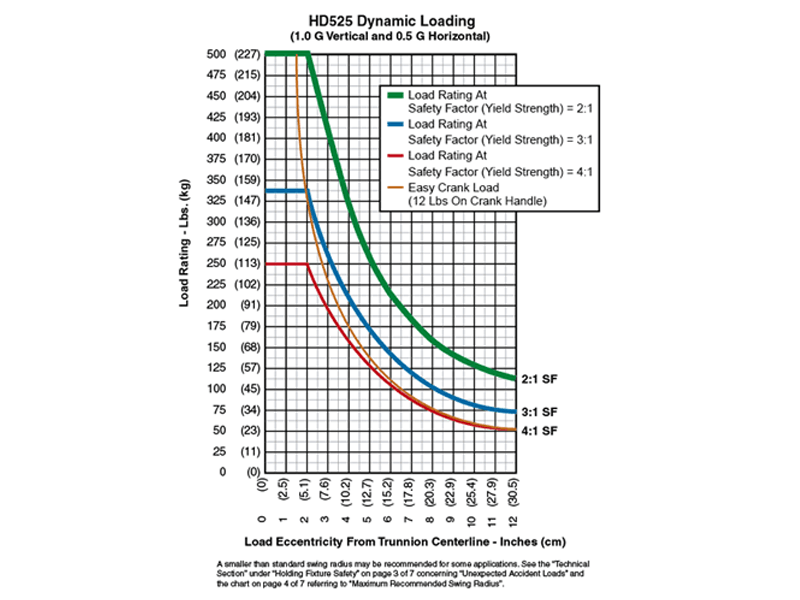
- Safety Factor: 2
- Rated Load Capacity:
- Dynamic, 0″ eccentricity: 500 lbs. (227 Kg.)
- Dynamic, 5″ eccentricity: 255 lbs. (116 Kg.)
- Operating Temperature: +32 to +104 °F (0 to +40 °C). Contact factory for special applications with extended operating temperatures.
- Choice of Trunnion Interface/Mount/Clamp Options:
- Angle Interface
- Mounting Plate Interface
- Board Clamp
- Choice of Main Beam Length
- Main Beam Ball Lock Pins: Reliably prevents End Frames from slipping on Main Beams
- Casters: 5″ diameter x 2″ wide wheel with polyurethane tread sealed swivel bearing and Tech-lock brake
- Gearbox: 50:1 ratio with 6″ diameter crank
- Materials: Steel construction
- Finish: Flotron Blue powder coat with selected parts zinc plated.
- Trunnion Brake Knob
- A smaller than standard swing radius may be recommended for some applications. See the “Technical Section” under “Holding Fixture Safety” on page 3 of 7 concerning “Unexpected Accident Loads” and the chart on page 4 of 7 referring to “Maximum Recommended Swing Radius”
- Optional Main Beam Lengths
- Optional Trunnion Interface/Mount/Clamp
- Optional Index Plate
- Optional Casters
- Optional finishes for clean room compatibility
- Optional Ground Lug and Drag Chain for use in electrostatically protected area (EPA’s)
- For more about 500 Series Options click here
All data presented is based on no modifications to the product.
As Flotron is constantly improving products and methods of manufacturing, we reserve the right to modify and/or change design or specifications without notice. Please contact Flotron for verification of critical dimensions and specifications.
For 500 Series – Creating a Model Number pdf click here
For clarification of terms or phrases, please see the Holding Fixtures Definitions page.
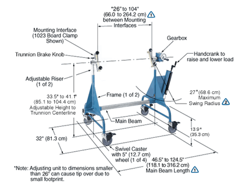
HD510-HYD Data Sheet
The Model HD510-HYD-1023-B048-C5SPX shown below is typical and representative of the HD510-HYD Models. For more information on specifying a holding fixture, see the 500 SERIES OPTIONS page and 500 SERIES CREATING A MODEL NUMBER pdf.
The maximum distance between mounting interfaces is directly related to the main beam length. Specify the distance between mounting interfaces to be at or slightly larger than the length of the part-to-be-handled. The fixture can be adjusted to accommodate smaller length parts, however, the main beam(s) extending from each end frame may be inconvenient. For more information see the
500 SERIES OPTIONS page and
500 SERIES CREATING A MODEL NUMBER pdf.
A smaller than standard swing radius may be recommended for some applications. See the “Technical Section” under “Holding Fixture Safety” on page 3 of 7 concerning “Unexpected Accident Loads” and the chart on page 4 of 7 referring to “Maximum Recommended Swing Radius”
Product Features:
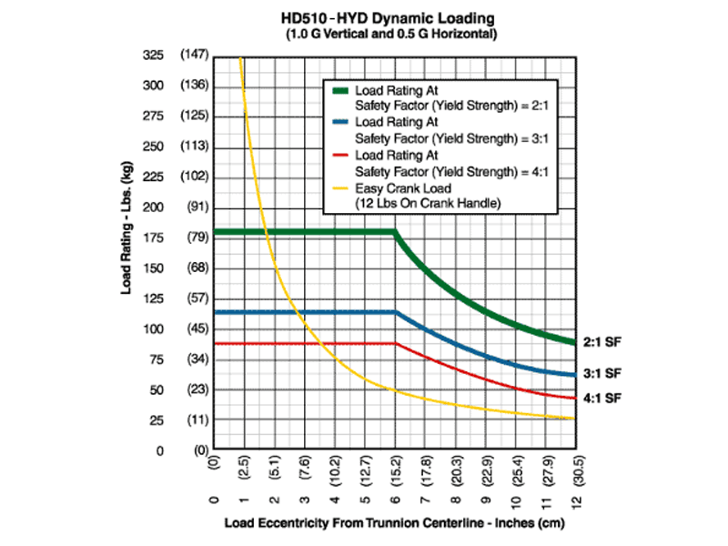
- Safety Factor: 2
- Rated Load Capacity:
- Dynamic, 0″ eccentricity: 175 lbs. (79 Kg.)
- Dynamic, 5″ eccentricity: 175 lbs. (79 Kg.)
- Note: The hydraulic cylinders are single acting and a minimum load of 30 lbs is recommended to activate the return (compression) stroke and to give good synchronization of the risers.
- Operating Temperature: +32 to +104 °F (0 to +40 °C). Contact factory for special applications with extended operating temperatures.
- Choice of Trunnion Interface/Mount/Clamp Options:
- Angle Interface
- Mounting Plate Interface
- Board Clamp
- Choice of Main Beam Length
- Main Beam Ball Lock Pins: Reliably prevents End Frames from slipping on Main Beams
- Casters: 5″ diameter x 1 ¼” wide wheel with Performa tread and Tech-lock brake
- Gearbox: 40:1 ratio with 4″ diameter crank
- Materials: Steel construction
- Finish: Flotron Blue powder coat with selected parts zinc plated.
- Trunnion Brake Knob
- A smaller than standard swing radius may be recommended for some applications. See the “Technical Section” under “Holding Fixture Safety” on page 3 of 7 concerning “Unexpected Accident Loads” and the chart on page 4 of 7 referring to “Maximum Recommended Swing Radius”
- Optional Gearbox: 50:1 ratio with 6″ diameter crank
- Optional Main Beam Lengths
- Optional Trunnion Interface/Mount/Clamp
- Optional Index Plate
- Optional Casters
- Optional finishes for clean room compatibility
- Optional Ground Lug and Drag Chain for use in electrostatically protected areas (EPA’s)
- For more about 500 Series Options click here
All data presented is based on no modifications to the product.
As Flotron is constantly improving products and methods of manufacturing, we reserve the right to modify and/or change design or specifications without notice. Please contact Flotron for verification of critical dimensions and specifications.
For 500 Series – Creating a Model Number pdf click here
For clarification of terms or phrases, please see the Holding Fixtures Definitions page.
HD510 Data Sheet
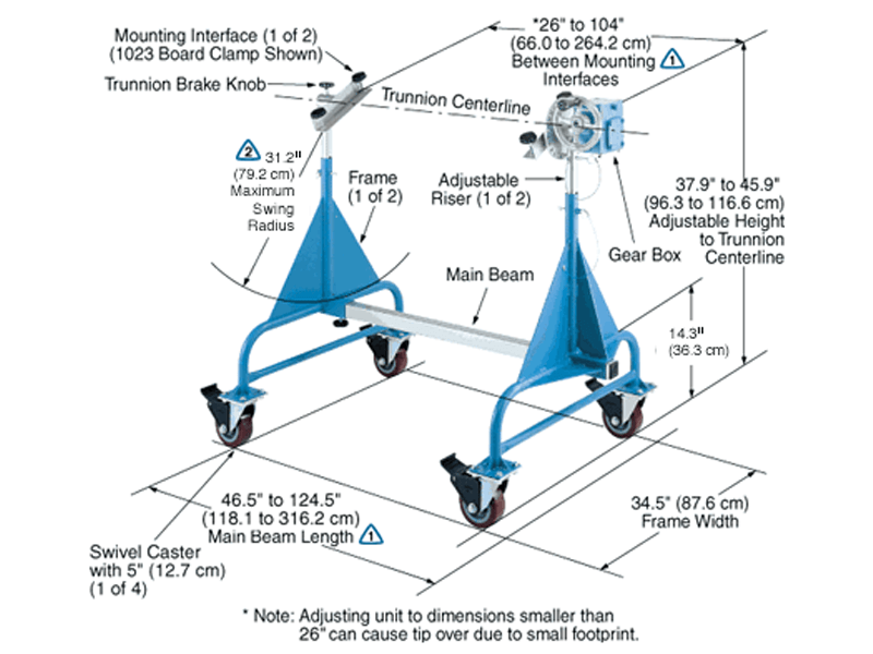
The Model HD510-1023-IND15-B048 shown below is typical and representative of the HD510 Models. For more information on specifying a holding fixture, see the 500 SERIES OPTIONS page and 500 SERIES CREATING A MODEL NUMBER pdf.
The maximum distance between mounting interfaces is directly related to the main beam length. Specify the distance between mounting interfaces to be at or slightly larger than the length of the part-to-be-handled. The fixture can be adjusted to accommodate smaller length parts, however, the main beam(s) extending from each end frame may be inconvenient. For more information see the
500 SERIES OPTIONS page and
500 SERIES CREATING A MODEL NUMBER pdf.
A smaller than standard swing radius may be recommended for some applications. See the “Technical Section” under “Holding Fixture Safety” on page 3 of 7 concerning “Unexpected Accident Loads” and the chart on page 4 of 7 referring to “Maximum Recommended Swing Radius”
Product Features:
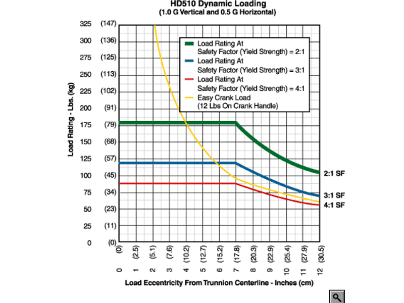
- Safety Factor: 2
- Rated Load Capacity:
- Dynamic, 0″ eccentricity: 175 lbs. (79 Kg.)
- Dynamic, 5″ eccentricity: 175 lbs. (79 Kg.)
- Operating Temperature: +32 to +104 °F (0 to +40 °C). Contact factory for special applications with extended operating temperatures.
- Choice of Trunnion Interface/Mount/Clamp Options:
- Angle Interface
- Mounting Plate Interface
- Board Clamp
- Choice of Main Beam Length
- Main Beam Ball Lock Pins: Reliably prevents End Frames from slipping on Main Beams
- Casters: 5″ diameter x 2″ wide wheel with polyurethane tread sealed swivel bearing and Tech-lock brake
- Gearbox: 50:1 ratio with 6″ diameter crank
- Materials: Steel construction
- Finish: Flotron Blue powder coat with selected parts zinc plated.
- Trunnion Brake Knob
- A smaller than standard swing radius may be recommended for some applications. See the “Technical Section” under “Holding Fixture Safety” on page 3 of 7 concerning “Unexpected Accident Loads” and the chart on page 4 of 7 referring to “Maximum Recommended Swing Radius”
- Optional Main Beam Lengths
- Optional Trunnion Interface/Mount/Clamp
- Optional Index Plate
- Optional Casters
- Optional finishes for clean room compatibility
- Optional Ground Lug and Drag Chain for use in electrostatically protected area (EPA’s)
- For more about 500 Series Options click here
All data presented is based on no modifications to the product.
As Flotron is constantly improving products and methods of manufacturing, we reserve the right to modify and/or change design or specifications without notice. Please contact Flotron for verification of critical dimensions and specifications.
For 500 Series – Creating a Model Number pdf click here
For clarification of terms or phrases, please see the Holding Fixtures Definitions page.
HD425 Data Sheet
The Model HD425-0000-B028-C5SPX shown below is typical and representative of the HD425 Models. For more information on specifying a holding fixture, see the 400 SERIES OPTIONS page and 400 SERIES CREATING A MODEL NUMBER pdf.
The maximum distance between mounting interfaces is directly related to the main beam length. Specify the distance between mounting interfaces to be at or slightly larger than the length of the part-to-be-handled. The fixture can be adjusted to accommodate smaller length parts, however, the main beam(s) extending from each end frame may be inconvenient. For more information see the
400 SERIES OPTIONS page and
400 SERIES CREATING A MODEL NUMBER pdf.
Addition of an optional index plate decreases the vertical adjustment from 10″ to 8″ and increases the minimum trunnion height from 35.5″ to 37.5″.
A smaller than standard swing radius may be recommended for some applications. See the “Technical Section” under “Holding Fixture Safety” on page 3 of 7 concerning “Unexpected Accident Loads” and the chart on page 4 of 7 referring to “Maximum Recommended Swing Radius”
Product Features:
- Safety Factor: 2
- Rated Load Capacity:
- Dynamic, 0″ eccentricity: 115 lbs. (52 kg.)
- Dynamic, 5″ eccentricity: 115 lbs. (52 kg.)
- Operating Temperature: +32 to +104 °F (0 to +40 °C). Contact factory for special applications with extended operating temperatures.
- Choice of Trunnion Interface/Mount/Clamp Options:
- Angle Interface
- Mounting Plate Interface
- Board Clamp Interface
- Choice of Main Beam Length
- Main Beam Ball Lock Pins: Reliably prevents End Frames from slipping on Main Beams
- Casters: 5″ diameter x 1 ¼” wide wheel with Performa tread and Tech Lock brake
- Gearbox: 40:1 ratio with 4″ diameter crank
- Materials: Steel construction
- Finish: Flotron Blue powder coat with selected parts zinc plated.
- Trunnion Brake Knob
- A smaller than standard swing radius may be recommended for some applications. See the “Technical Section” under “Holding Fixture Safety” on page 3 of 7 concerning “Unexpected Accident Loads” and the chart on page 4 of 7 referring to “Maximum Recommended Swing Radius”
- Optional Main Beam Lengths or Telescopic Main Beam
- Optional Trunnion Interface/Mount/Clamp
- Optional Index Plate
- Optional Casters
- Optional Gear Box: 50:1 ratio with 6″ diameter crank
- Optional finishes for clean room compatibility
- Optional Ground Lug and Drag Chain for use in electrostatically protected areas (EPA’s)
- For more about 400 Series Options click here
All data presented is based on no modifications to the product.
As Flotron is constantly improving products and methods of manufacturing, we reserve the right to modify and/or change design or specifications without notice. Please contact Flotron for verification of critical dimensions and specifications.
For 400 Series – Creating a Model Number pdf click here.
For clarification of terms or phrases, please see the Holding Fixtures Definitions page.
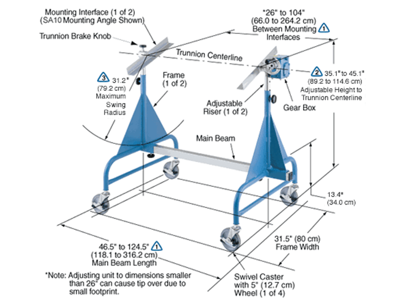
HD410 Data Sheet
The Model 410-1018-B048-5 shown below is typical and representative of the 410 Models. For more information on specifying a holding fixture, see the 400 SERIES OPTIONS page and 400 SERIES CREATING A MODEL NUMBER pdf.
The maximum distance between mounting interfaces is directly related to the main beam length. Specify the distance between mounting interfaces to be at or slightly larger than the length of the part-to-be-handled. The fixture can be adjusted to accommodate smaller length parts, however, the main beam(s) extending from each end frame may be inconvenient. For more information see the
400 SERIES OPTIONS page and
400 SERIES CREATING A MODEL NUMBER pdf.
Addition of an optional index plate decreases the vertical adjustment from 10″ to 8″ and increases the minimum trunnion height from 35.1″ to 37.1″.
A smaller than standard swing radius may be recommended for some applications. See the “Technical Section” under “Holding Fixture Safety” on page 3 of 7 concerning “Unexpected Accident Loads” and the chart on page 4 of 7 referring to “Maximum Recommended Swing Radius”
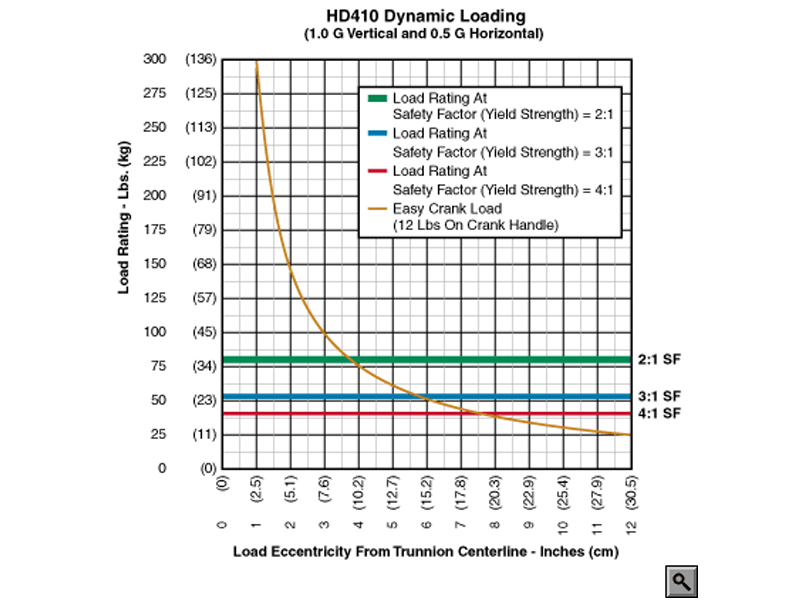
Product Features:
- Safety Factor: 2
- Rated Load Capacity:
- Dynamic, 0″ eccentricity: 80 lbs. (36 kg.)
- Dynamic, 5″ eccentricity: 80 lbs. (36 kg.)
- Operating Temperature: +32 to +104 °F (0 to +40 °C). Contact factory for special applications with extended operating temperatures.
- Choice of Trunnion Interface/Mount/Clamp Options:
- Angle
- Mounting Plate
- Board Clamp
- Choice of Main Beam Length
- Main Beam Ball Lock Pins: Reliably prevents End Frames from slipping on Main Beams
- Casters: 5″ diameter x 7/8″ wide wheel with Performa tread and metal sidelock brake
- Gearbox: 40:1 ratio with 4″ diameter crank
- Materials: Steel construction
- Finish: Flotron Blue powder coat with selected parts zinc plated.
- Trunnion Brake Knob
- A smaller than standard swing radius may be recommended for some applications. See the “Technical Section” under “Holding Fixture Safety” on page 3 of 7 concerning “Unexpected Accident Loads” and the chart on page 4 of 7 referring to “Maximum Recommended Swing Radius”
- Optional Main Beam Lengths
- Optional Trunnion Interface/Mount/Clamp
- Optional Index Plate
- Optional Casters
- Optional Gear Box: 50:1 ratio with 6″ diameter crank
- Optional finishes for clean room compatibility
- Optional Ground Lug and Drag Chain for use in electrostatically protected areas (EPA’s)
- For more about 400 Series Options click here
All data presented is based on no modifications to the product.
As Flotron is constantly improving products and methods of manufacturing, we reserve the right to modify and/or change design or specifications without notice. Please contact Flotron for verification of critical dimensions and specifications.
For 400 Series – Creating a Model Number pdf click here.
For clarification of terms or phrases, please see the Holding Fixtures Definitions page.