Archives
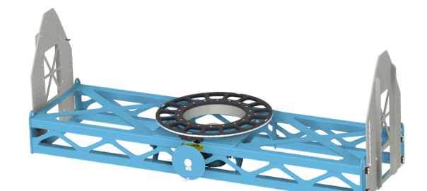
Cantilevered Rotation Fixtures
Flotron’s off‐the‐shelf cantilevered rotation fixture is designed to be a cost-effective solution to allow ergonomic full access to cantilevered payloads. The CRF design intent is to support small satellites or satellite instruments during assembly, integration and test activities. The spaceflight hardware can be supported in a cantilevered orientation so that the longitudinal axis is parallel to the floor and then rotated 360 degrees.
XD747
XD747 Data Sheet
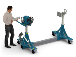
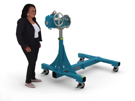
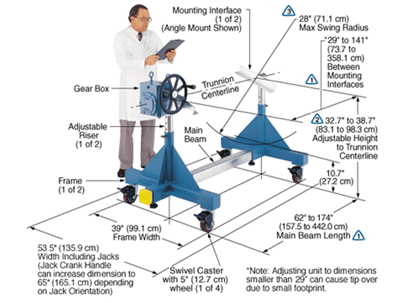
The Model XD747-P8-B052 shown below is typical and representative of the XD747 Models. For more information on specifying a holding fixture, see the 700 SERIES OPTIONS page and 700 SERIES CREATING A MODEL NUMBER pdf.

The maximum distance between mounting interfaces is directly related to the main beam length. Specify the distance between mounting interfaces to be at or slightly larger than the length of the part-to-be-handled. The fixture can be adjusted to accommodate smaller length parts, however, the main beam(s) extending from each end frame may be inconvenient. For more information see the 700 SERIES OPTIONS page and 700 SERIES CREATING A MODEL NUMBER pdf.
Addition of the optional SR or DR gearbox decreases the vertical riser adjustment from 8″ to 6″ and increases the minimum trunnion height from 38.7″ to 40.7″.
A smaller than standard swing radius may be recommended for some applications. See the “Technical Section” under “Holding Fixture Safety” on page 3 of 7 concerning “Unexpected Accident Loads” and the chart on page 4 of 7 referring to “Maximum Recommended Swing Radius”
Product Features:
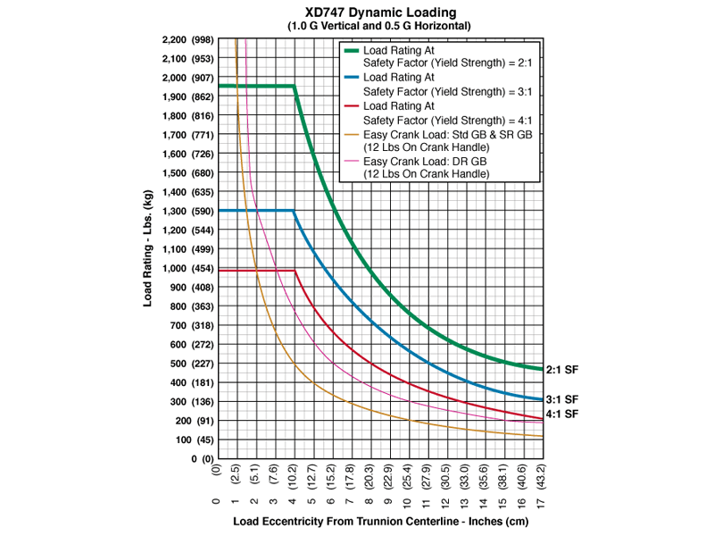
- Safety Factor: 3
- Rated Load Capacity:
- Dynamic, 0″ eccentricity: 1,300 lbs. (590 kg.)
- Dynamic, 5″ eccentricity: 1,080 lbs. (490 kg.)
- Operating Temperature: +32 to +104 °F (0 to +40 °C). Contact factory for special applications with extended operating temperatures.
- Choice of Trunnion Interface/Mount/Clamp Options:
- Angle Interface
- Mounting Plate Interface
- Choice of Main Beam Length
- Main Beam Ball Lock Pins: Reliably prevents End Frames from slipping on Main Beams
- Gearbox: 60:1 ratio with 12″ diameter crank
- Casters: 5″ diameter x 2″ wide wheel with polyurethane tread, sealed swivel bearing and Tech-lock brake
- Materials: Steel construction
- Finish: Flotron Blue powder coat with selected parts zinc plated.
- A smaller than standard swing radius may be recommended for some applications. See the “Technical Section” under “Holding Fixture Safety” on page 3 of 7 concerning “Unexpected Accident Loads” and the chart on page 4 of 7 referring to “Maximum Recommended Swing Radius”
- Optional Main Beam lengths
- Optional Trunnion Interface/Mount/Clamp
- Optional Index Plate
- Optional Index Stops
- Optional Casters
- Optional Leveling Jacks
- Optional Gearboxes incorporating heavy duty, low backlash and stairstep resistant features
- Optional finishes for clean room compatibility
- Optional Ground Lug and Drag Chain for use in electrostatically protected areas (EPA’s)
- For more about 700 Series Options click here
All data presented is based on no modifications to the product.
As Flotron is constantly improving products and methods of manufacturing, we reserve the right to modify and/or change design or specifications without notice. Please contact Flotron for verification of critical dimensions and specifications.
For 700 Series – Creating a Model Number pdf click here.
For clarification of terms or phrases, please see the Holding Fixtures Definitions page.
XD739
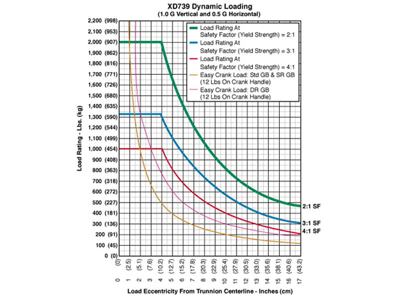
XD739 Data Sheet
The Model XD739-A18-B043 shown below is typical and representative of the XD739 Models. For more information on specifying a holding fixture, see the 700 SERIES OPTIONS page and 700 SERIES CREATING A MODEL NUMBER pdf.
The maximum distance between mounting interfaces is directly related to the main beam length. Specify the distance between mounting interfaces to be at or slightly larger than the length of the part-to-be-handled. The fixture can be adjusted to accommodate smaller length parts, however, the main beam(s) extending from each end frame may be inconvenient. For more information see the 700 SERIES OPTIONS page and 700 SERIES CREATING A MODEL NUMBER pdf.
Addition of the optional SR or DR gearbox decreases the vertical riser adjustment from 6″ to 4″ and increases the minimum trunnion height from 32.7″ to 34.7″.
A smaller than standard swing radius may be recommended for some applications. See the “Technical Section” under “Holding Fixture Safety” on page 3 of 7 concerning “Unexpected Accident Loads” and the chart on page 4 of 7 referring to “Maximum Recommended Swing Radius”
Product Features:
- Safety Factor: 3
- Rated Load Capacity:
- Dynamic, 0″ eccentricity: 1,330 lbs. (603 kg.)
- Dynamic, 5″ eccentricity: 1,080 lbs. (490 kg.)
- Operating Temperature: +32 to +104 °F (0 to +40 °C). Contact factory for special applications with extended operating temperatures.
- Choice of Trunnion Interface/Mount/Clamp Options:
- Angle Interface
- Mounting Plate Interface
- Choice of Main Beam Length
- Main Beam Ball Lock Pins: Reliably prevents End Frames from slipping on Main Beams
- Gearbox: 60:1 ratio with 12″ diameter crank
- Casters: 5″ diameter x 2″ wide wheel with polyurethane tread, sealed swivel bearing and Tech-lock brake
- Materials: Steel construction
- Finish: Flotron Blue powder coat with selected parts zinc plated.
- A smaller than standard swing radius may be recommended for some applications. See the “Technical Section” under “Holding Fixture Safety” on page 3 of 7 concerning “Unexpected Accident Loads” and the chart on page 4 of 7 referring to “Maximum Recommended Swing Radius”
- Optional Main Beam Lengths
- Optional Trunnion Interface/Mount/Clamp
- Optional Index Plate
- Optional Index Stops
- Optional Casters
- Optional Leveling Jacks
- Optional Gearboxes incorporating heavy duty, low backlash and stairstep resistant features
- Optional finishes for clean room compatibility
- Optional Ground Lug and Drag Chain for use in electrostatically protected areas (EPA’s)
- For more about 700 Series Options click here
All data presented is based on no modifications to the product.
As Flotron is constantly improving products and methods of manufacturing, we reserve the right to modify and/or change design or specifications without notice. Please contact Flotron for verification of critical dimensions and specifications.
For 700 Series – Creating a Model Number pdf click here.
For clarification of terms or phrases, please see the Holding Fixtures Definitions page.
Dual Support Cradles
Flotron’s Dual Support Cradles (DSC) are designed to turn a standard rotation fixture into a dual axis of rotation fixture. The DSC is for cantilevered payloads that require both tilting and 360° rotation. There are different capacity cradles for different payload weights and the larger cradle features the option to have gearbox driven rotation on the secondary axis of rotation. The DSC-P1 was designed to be used with Flotron’s XD739, XD747, or SFP-645 series dual support fixtures. The DSC-P2 and DSC-G2 were designed to be used with Flotron’s SFP-759, SFP-853, or SFP-862 series dual support fixtures. The cradles can be used with other rotation fixtures if the capacity is rated high enough and swing clearance is sufficient. The cradles have been optimized for both high strength and low weight with advanced FEA software. Custom length cradles are available upon request in 20” increments for payloads that require more (or less) swing radius clearance than the standard. The load rating may be lower for longer cradles than standard.
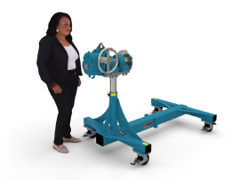
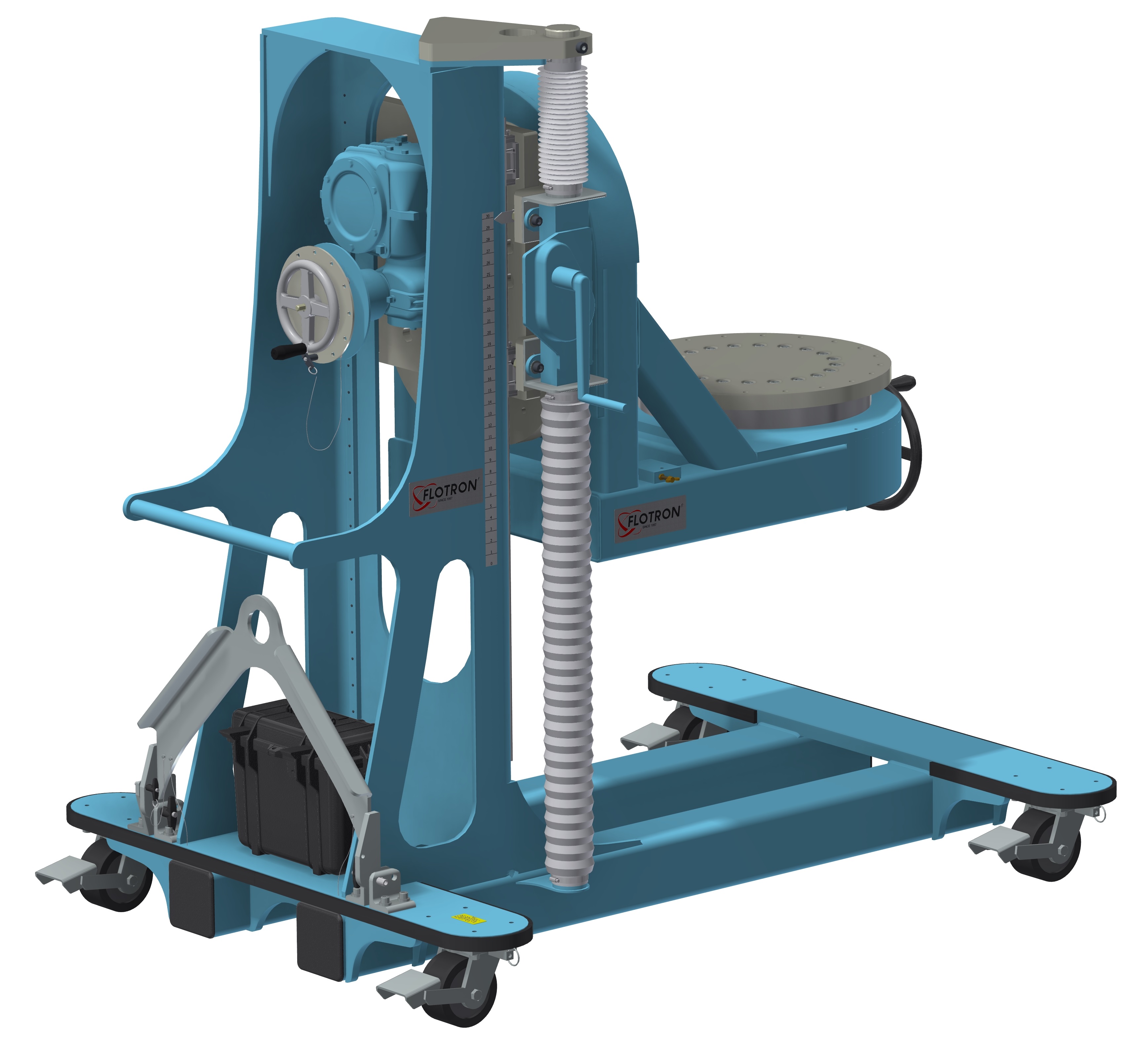
CRF 36
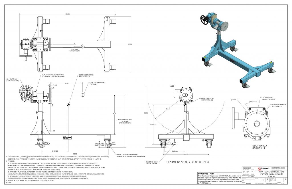
CRF 36 Data Sheet
The Model CRF-36‐P12‐C6 shown below is typical and representative of the CTL 36 Models. For more information on specifying a cantilevered rotation fixture, see the CANTILEVERED ROTATION FIXTURE page and CANTILEVERED ROTATION FIXTURE CREATING A MODEL NUMBER pdf.
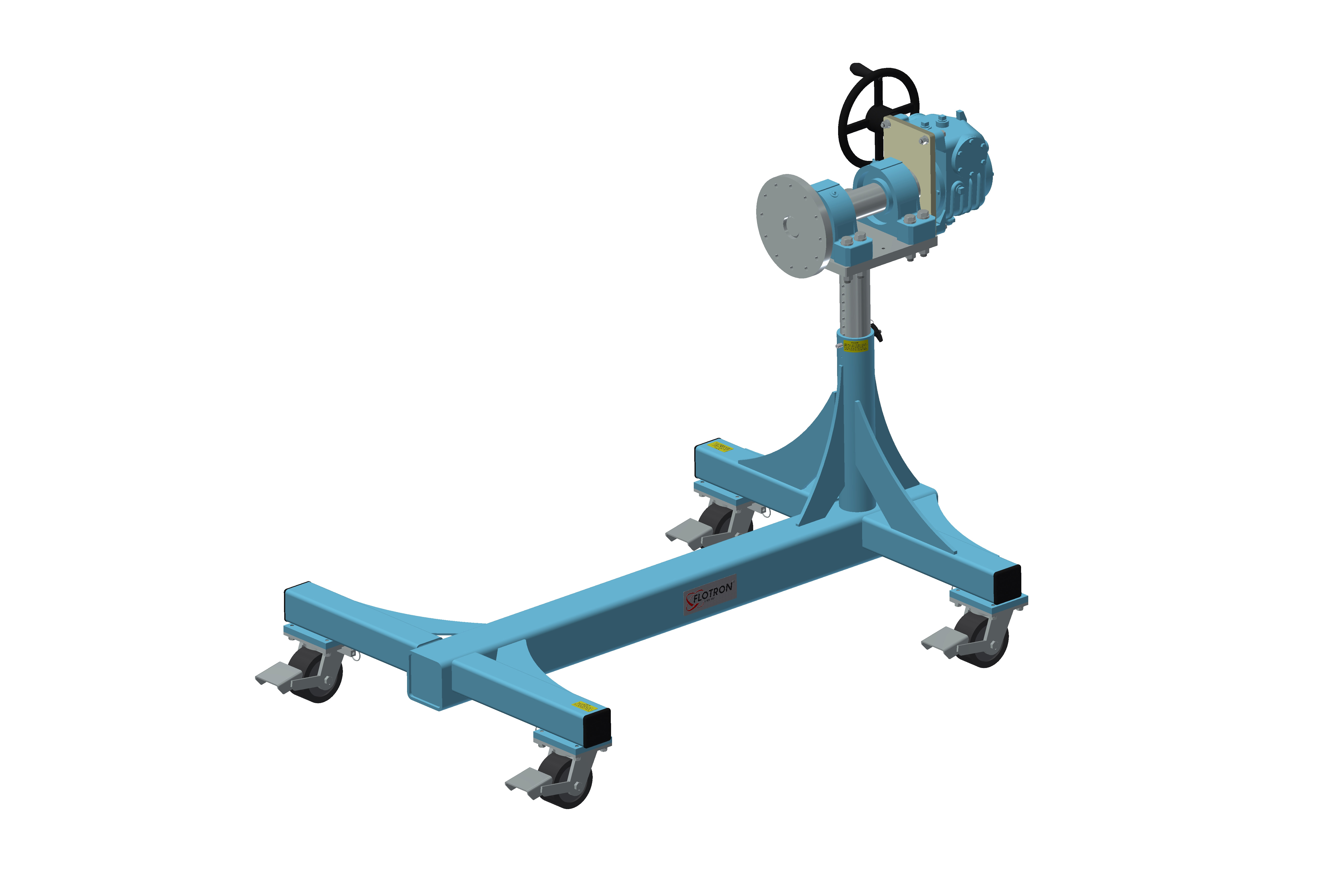
Product Features:
- Safety Factors: 3 for Yield & 5 for Ultimate
- Rated Load Capacity: 1,000 lbs. with CG located at 30” from interface plate and 2” from primary axis rotation centerline.
- Operating Temperature: +32 to +104 °F (0 to +40 °C). Contact factory for special applications with extended operating temperatures.
- Payload Interface: Ø12” Circular Interface Plate with 12X through holes for 1/2” fasteners on Ø10” bolt circle.
- Gearbox: 60:1ratio with 12” diameter crank.
- Casters: Heavy duty 6″ diameter x 3″ wide phenolic tread, sealed bearings, swivel lock, brake, and steering bar receptacles. (Ø12” diameter optional)
- Materials: Steel construction.
- Finish: Flotron Blue powder coat with selected parts zinc plated.
- Optional Casters.
- Optional Lubricants.
- Optional Tow Bar.
- Optional finishes for clean room compatibility.
- Optional Ground Lug and Drag Chain for use in electrostatically protected areas (EPA’s).
- Optional Standard Proof Load Test.
- For more about Cantilevered Rotation Fixture Options click here.
All data presented is based on no modifications to the product.
As Flotron is constantly improving products and methods of manufacturing, we reserve the right to modify and/or change design or specifications without notice. Please contact Flotron for verification of critical dimensions and specifications.
For Cantilevered Rotation Fixtures – Creating a Model Number pdf click here.
For clarification of terms or phrases, please see the Holding Fixtures Definitions page.
Integration Fixtures

Panel Integration Fixture
Panel integration fixture capable of integrating panels with a space vehicle.
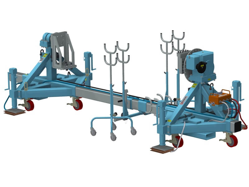
Pylon Integration Fixture
Pylon integration fixture with long stroke lift jacks capable of lifting and attaching the pylon onto a strong back. An air caster system has been incorporate to float the loaded Flotron over smooth sealed surfaces.

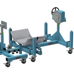
Fuel Tank Integration
Fuel tank integration fixture with lift and translate cradle designed to support the installation of a fuel tank into a composite structure. The non-gearbox-side end frame is rolled away during integration.

Missile Integration Fixture
Pod integration fixture with cross bar rollers capable of rolling and translating pod shaped payloads during assembly.
Battery Integration Fixture
Battery integration fixture with cantilevered end effector that provides six degrees of freedom to align battery during installation.
Cantilevered
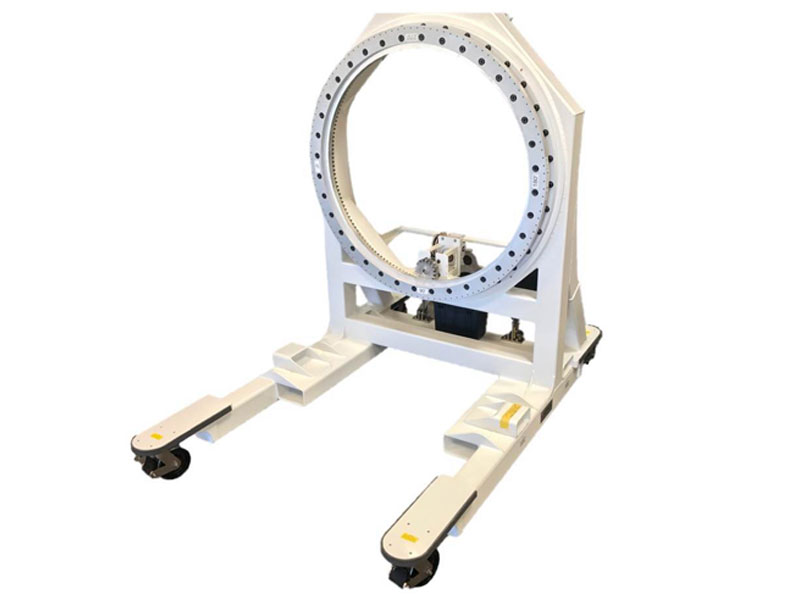
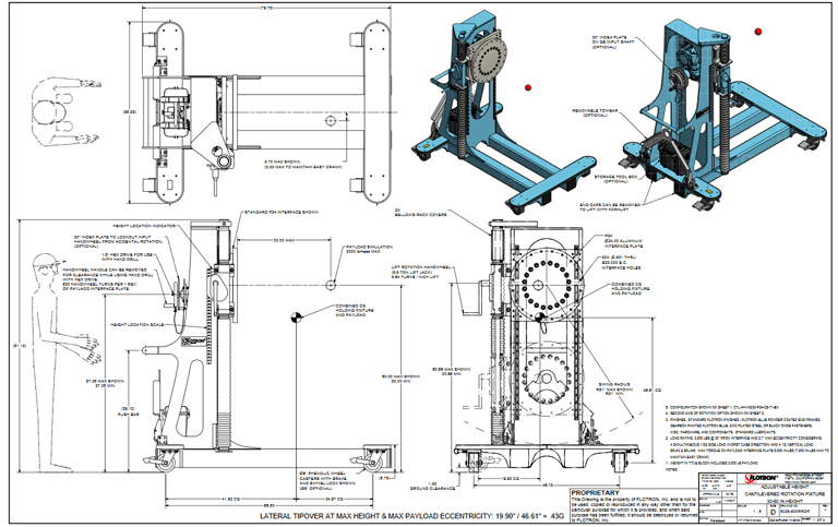
Cantilevered Satellite Integration Fixture
There are cases where spacecraft integration requires an access hole thru the payload mounting interface. This access may be required for instrument integration, propulsion integration, spacecraft wiring ... etc. To provide a scale of the size of the Flotron represented in the image below, the available payload swing diameter (as measured from the rotation centerline) is Ø110" and the ID of the slew ring is approximately Ø54". This cantilevered satellite integration fixture can support high moment and radial loads considering SFy = 3 and SFu = 5 in addition to a simultaneous (horizontal and vertical) dynamic loading condition. The resultant stability (with payload integrated) is 0.75G. The payload can be rotated 360° either by hand crank or by interfacing with a socket and electric hand drill. The gear drive is self-locking and non-back-driving with minimal backlash and the index plate on the input shaft can be physically pinned. The payload mounting interface dimensions and tolerances were specified by our customer. The finishes are compatible in a CLASS 10K clean room spacecraft manufacturing environment (no zinc, tin, or cadmium) and the lubricants were selected for compatibility. Covers were added over the geared slew ring and pinion gear to eliminate pinch points and to mitigate lubricant migration. The operator can maneuver the Rotation Fixture by the push bar or the tow bar. Forklift tube pockets have been incorporated at the rear to lift the Flotron (with the payload integrated) as well as at the side to handle the empty Flotron. The caster wheel material and geometry were specified to optimize rollability. Additional features include leg bumpers, relevant caution labels, angular indicator labels, and a storage container. Flotron fabricated a 2X proof load test simulator that represents 200% payload weight, 200% resultant moment and 100% torque. Flotron performed a proof load test with the payload simulator integrated when supported by the casters as wells as when lifted with a forklift. Weld inspection of critical welds (as defined by Flotron Engineering) was performed using an Eddy Current inspection method through the powder coat finish.
Customer Review:
The spacecraft mated to the Flotron fixture, all features were exercised to the delight of our customer and it is working excellent! Thank you again for the fine craftsmanship that your team delivered on.
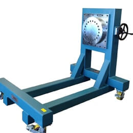
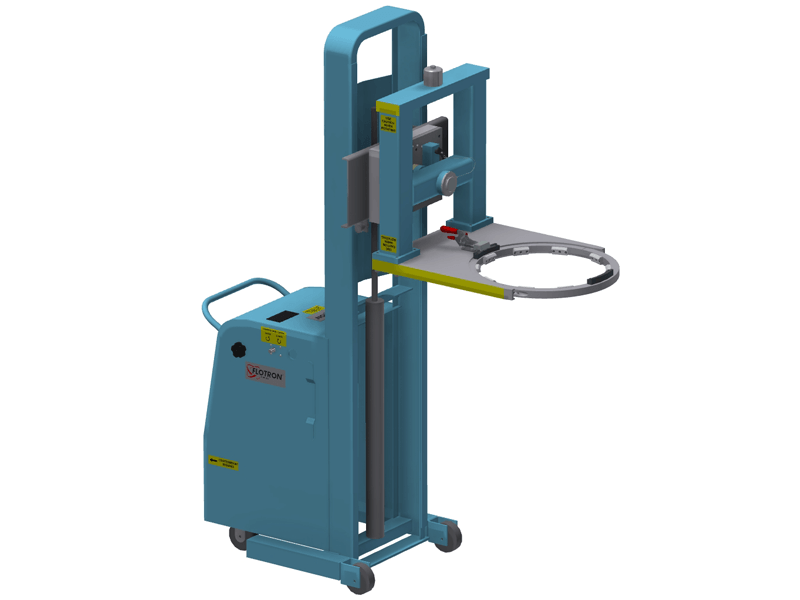
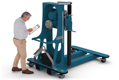
High Moment Capacity Cantilevered Rotation
Flotron’s customers typically interface their payload at both ends. However, there are cases where the payload has only a single mounting interface and in these cases the payload needs to be supported in a cantilevered configuration. Flotron’s Cantilevered Rotation Fixtures have been utilized for a myriad of applications including spacecraft positioning, small satellite AI&T, radar system RF testing, among others. This Aerospace Tool is designed considering that the payload CG will be located at a significant distance from the mounting interface and that there will be a high resultant moment load. The geared bearing that Flotron has selected to accommodate these high moment loads can also accommodate higher radial loads and therefore the CG of the payload can be further off of the rotational centerline and still offer ergonomic rotation for the technician. Flotron also has the capability to design and manufacture custom end effectors and tooling interface hardware to adapt to complex payload geometry.
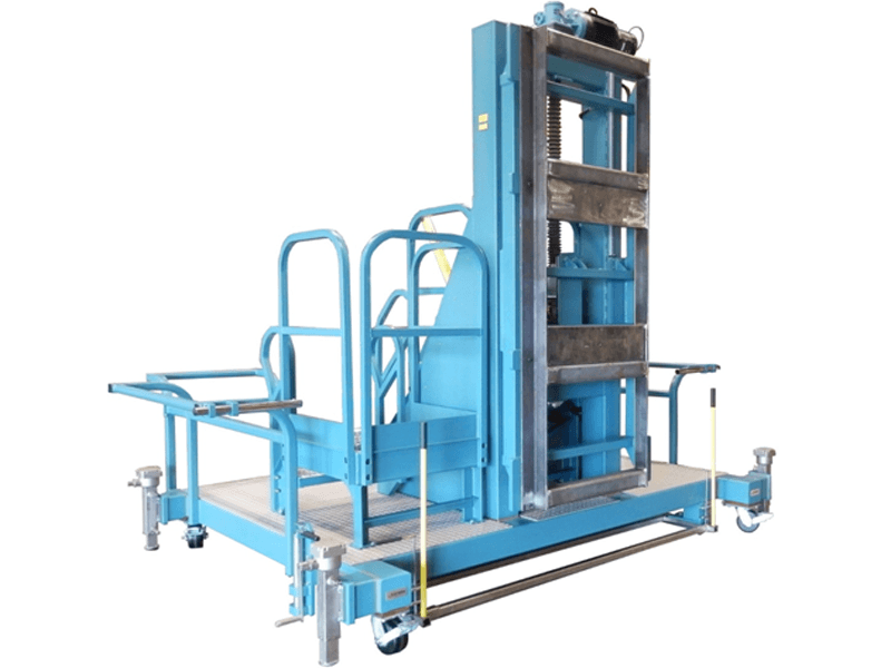
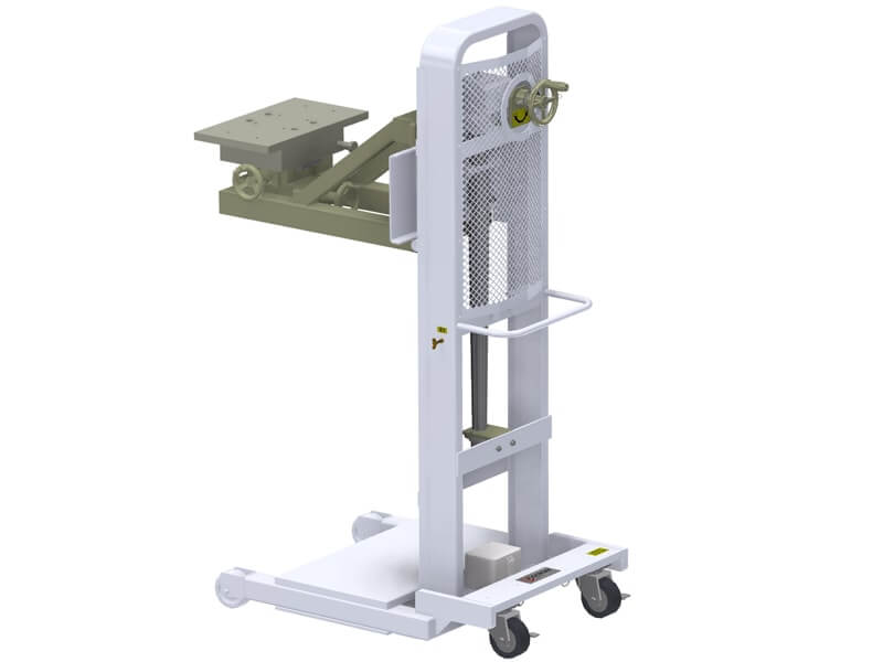
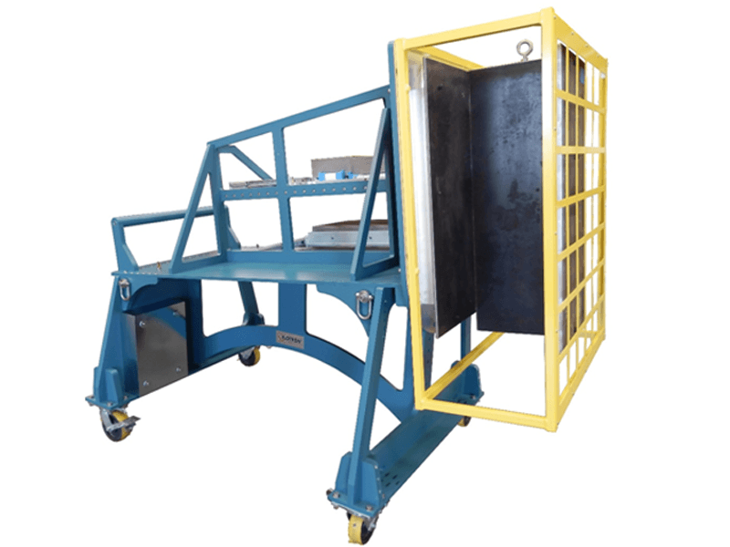
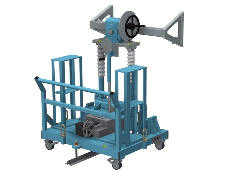
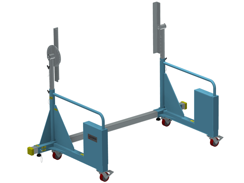
Motorized Height Adjustment with Working Platform
In the example below, a work station provides ergonomic access for technicians to offload a solar array wing from an overhead linear guide rail system, then pivot the work station (with wing attached) 90 degrees about a floor anchor and finally offload and deploy the solar array wing onto another overhead linear guide rail system. Finishes and lubricants are compatible in an ISO 14644-1, (Class ISO 7) / FED STD 209E (Class 10,000) clean room spacecraft manufacturing environment. In addition to providing mechanical lift systems that are actuated using an input hand crank, Flotron offers Aerospace Tools with electro-mechanical lift systems that are actuated with a pendant or control panel and have push button operation. Flotron incorporates UL approved controls and safety is considered first. There are multiple accessible safety stops, various operator presence sensing device options, limit switches, redundant braking, and audible / visual alerts among others.
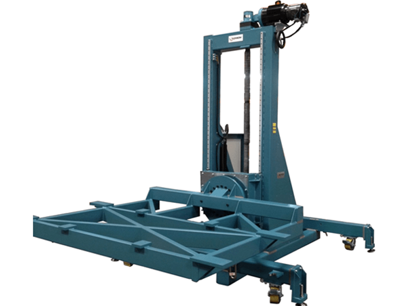
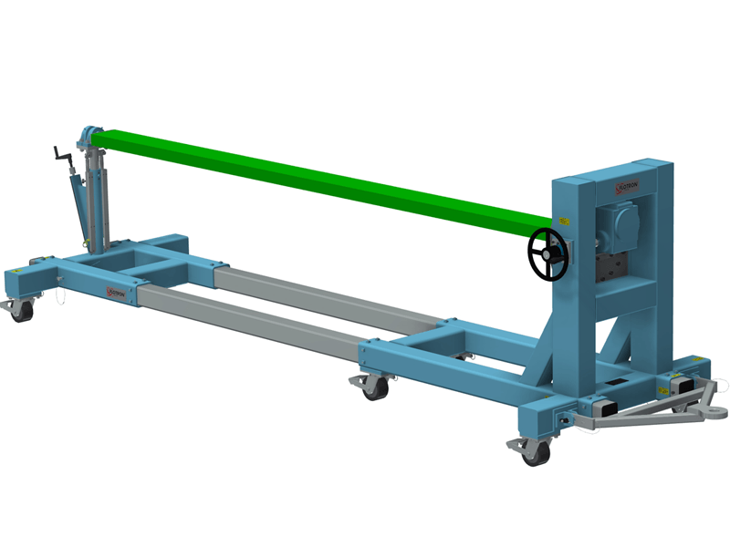
Cantilevered, Motorized Rotation and Height Adjustment
The Aerospace Tool above has both electro-mechanical lift and rotation functionality. This up-ender is used to offload individual rigid solar array panels from Flotron Rotation Fixtures one at a time into a stack. The panel stack is fastened together, lifted for clearance, tilted 90 degrees and then offloaded onto an overhead linear guide rail system. Finishes and lubricants are compatible in an ISO 14644-1, (Class ISO 7) / FED STD 209E (Class 10,000) clean room spacecraft manufacturing environment. In addition to providing mechanical lift and rotation systems that are actuated using an input hand crank, Flotron offers Aerospace Tools with electro-mechanical lift systems that are actuated with a pendant or control panel and have push button operation. Flotron incorporates UL approved controls and safety is considered first. There are multiple accessible safety stops, various operator presence sensing device options, limit switches, redundant braking, and audible / visual alerts among others.
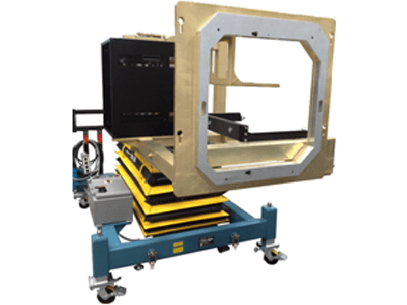
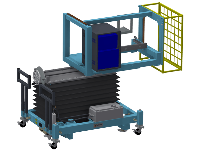
Cantilevered, Motorized Height Adjustment with Scissor Lift
In almost all cases, Flotron's Cantilevered Aerospace Tool Designs incorporate a tower structure that the payload cantilevers from. In the example below however, we utilized an electromechanical scissor lift to fulfill a vertical lifting requirement and then sized the scissor lift appropriately to accommodate an overhung cantilevered moment load. The scissor lift has a redundant belt driven lift mechanism and does not bleed down like a hydraulic system would. A tubular aluminum weldment / payload interface structure is fastened to a pair of precision linear guide bearing rails that in turn mount to the top of the scissor lift via an adapter plate. The tubular weldment (with payload cantilevered off of one end) can be translated horizontally with a ball screw and then locked into position. The caster jacks lower the RF Test Cart / Precision Alignment Fixture so that a series of three precision alignment tooling features seat in their respective floor mounted receptacles. A precision slide is then translated at the back to pivot this Pointing Fixture (with payload integrated) and align for an RF testing application. In addition to providing mechanical lift systems that are actuated using an input hand crank, Flotron offers Aerospace Tools with electro-mechanical lift systems that are actuated with a pendant or control panel and have push button operation. Flotron incorporates UL approved controls and safety is considered first. There are multiple accessible safety stops, various operator presence sensing device options, limit switches, redundant braking, and audible / visual alerts among others.
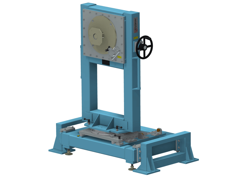
Thermal Cycle Compatible
This aluminum Cantilevered Fixture also functions as an RF Test Fixture, Thermal Test Fixture and Transportation Fixture. It is compatible in both RF testing and thermal environments. The entire structure is bolted together and Flotron had to consider both mean and fatigue stresses resulting from both mechanical and thermal loads. The base frame is counter-weighted to maintain 0.5G horizontally stability. At a later stage of processing, this Cantilevered Fixture is bolted to the top of a Flotron designed Alignment Fixture to position and orient a payload for RF testing.
Cantilevered Lift and Rotation Fixture
Cantilevered lift and rotation fixture with custom counterweighted interface frame that secures hemispherical payload with latching mechanism.
Rocket Nozzle Welding, Brazing and Inspection Fixture
Cantilevered rotation fixture that supports large nozzle payloads during welding, brazing and x-ray operations.
RF Testing Work Station with Docking Features
Cantilevered rotation, lift and translate fixture with custom payload interface and docking features.
Cantilevered Wing Fixture
Cantilevered rotation fixture with high moment load capacity and payload support at opposite end with raise and lower capability.
Near Field Test Cart with Precision Alignment
Cantilevered electromechanical lift, manual translation and a custom interface structure that supports various payloads in their flight configuration.

Thermal Compatible Near Field Test Cart
Cantilevered fixture compatible in an oven with docking features and a custom interface structure that supports various payloads in their flight configuration.
RF Testing Work Station
Cantilevered lift, rotation and translation fixture with precision alignment features.
RF Test Fixture
Cantilevered rotation fixture with asymmetric counterweighted frame.
CTL-AH
CTL-AH Data Sheet
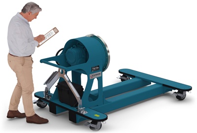
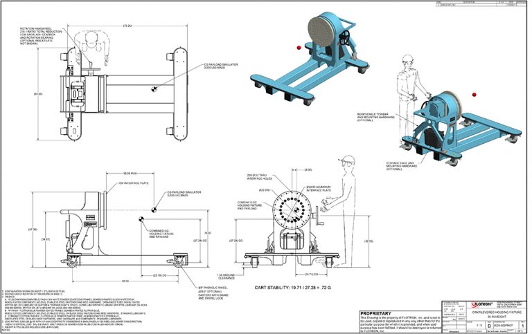
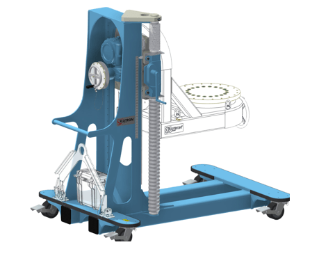
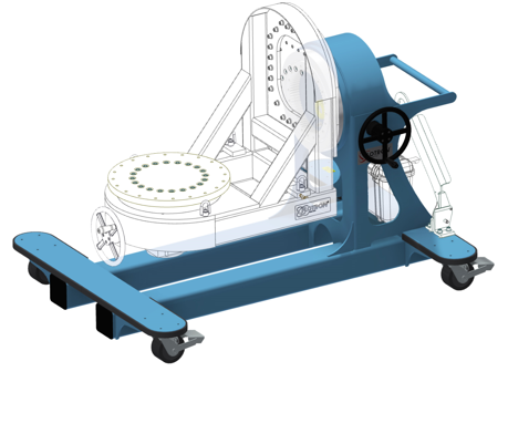
The Model CTL‐AH‐P24‐C6‐T1‐BX shown below is typical and representative of the CTL‐AH Models. For more information on specifying a cantilevered rotation fixture, see the SMALL SATELLITE FIXTURE OPTIONS page and SMALL SATELLITE FIXTURE CREATING A MODEL NUMBER pdf.
Product Features:
- Safety Factor: 3
- Rated Load Capacity: 3,000 lbs with CG located at 30” from interface plate and 2.7” from rotation centerline.
- Lift Range: 30”‐60” from floor to center of rotation.
- Operating Temperature: +32 to +104 °F (0 to +40 °C). Contact factory for special applications with extended operating temperatures.
- Payload Interface: Ø24” Circular Interface Plate with 20X through holes for 1⁄2” fasteners on Ø22” bolt circle.
- Gearbox: 175:1 ratio with 8′′ diameter crank.
- Slewing Ring: 3.6:1 ratio.
- Rack and Pinion Jack: 5.64 turns per inch lift.
- Casters: Heavy duty 6′′ diameter x 3′′ wide wheel with phenolic tread, sealed swivel bearing. Tech‐lock brake and swivel locks. (8” diameter optional).
- Materials: Steel and aluminum construction.
- Finish: Flotron Blue powder coat with selected parts zinc plated.
- Optional Index Plate.
- Optional Casters.
- Optional Tow Bar.
- Optional Tool Box.
- Optional finishes for clean room compatibility.
- Optional Ground Lug and Drag Chain for use in electrostatically protected areas (EPA’s).
- For more about Small Satellite Fixture Options click here.
All data presented is based on no modifications to the product.
As Flotron is constantly improving products and methods of manufacturing, we reserve the right to modify and/or change design or specifications without notice. Please contact Flotron for verification of critical dimensions and specifications.
For Small Satellite Fixture – Creating a Model Number pdf click here.
For clarification of terms or phrases, please see the Holding Fixtures Definitions page.
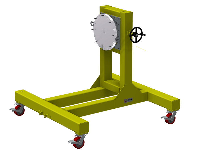
CTL36
CTL36 Data Sheet
The Model CTL36‐P24‐C6‐T1‐BX shown below is typical and representative of the CTL36 Models. For more information on specifying a cantilevered rotation fixture, see the SMALL SATELLITE FIXTURE OPTIONS page and SMALL SATELLITE FIXTURE CREATING A MODEL NUMBER pdf.

Product Features:
- Safety Factor: 3
- Rated Load Capacity: 3,000 lbs with CG located at 30” from interface plate and 2.6” from rotation centerline.
- Operating Temperature: +32 to +104 °F (0 to +40 °C). Contact factory for special applications with extended operating temperatures.
- Trunnion Interface/Mount/Clamp Options: Ø24” Circular Interface Plate with 20X through holes for ½” fasteners on Ø22” bolt circle.
- Gearbox: 60:1 ratio with 12″ diameter crank.
- Casters: Heavy duty 6″ diameter x 3″ wide wheel with phenolic tread, sealed swivel bearing. Tech‐lock brake and swivel locks.
- Materials: Steel construction.
- Finish: Flotron Blue powder coat with selected parts zinc plated.
- Optional Index Plate.
- Optional Casters.
- Optional Tow Bar.
- Optional Tool Box.
- Optional finishes for clean room compatibility.
- Optional Ground Lug and Drag Chain for use in electrostatically protected areas (EPA’s).
- For more about Small Satellite Fixture Options click here.
All data presented is based on no modifications to the product.
As Flotron is constantly improving products and methods of manufacturing, we reserve the right to modify and/or change design or specifications without notice. Please contact Flotron for verification of critical dimensions and specifications.
For Small Satellite Fixture – Creating a Model Number pdf click here.
For clarification of terms or phrases, please see the Holding Fixtures Definitions page.