Archives
SFP-747-EML
SFP-759
SFP-747
XD759-EML
XD747-EML
XD739-EML
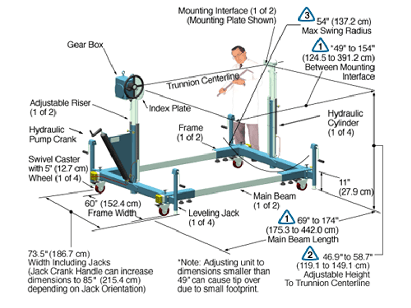
XD759DB-HYD
XD759DB-HYD Data Sheet
The Model XD759DB-HYD-J2-IND15-P8-B078 shown below is typical and representative of the XD759DB-HYD Models. For more information on specifying a holding fixture, see the 700 SERIES OPTIONS page and 700 SERIES CREATING A MODEL NUMBER pdf.
Product Features:
- Safety Factor: 3
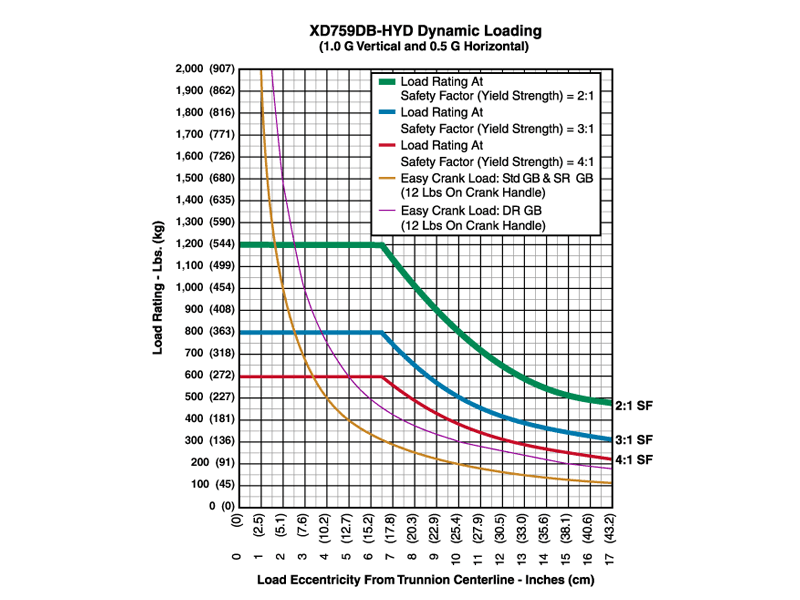
- Rated Load Capacity:
- Dynamic, 0″ eccentricity: 800 lbs. (363 kg.)
- Dynamic, 5″ eccentricity: 800 lbs. (363 kg.)
- Note: The hydraulic cylinders are single acting and a minimum load of 150 lbs is recommended to activate the return (compression) stroke and to give good synchronization of the risers.
- Operating Temperature: +32 to +104 °F (0 to +40 °C). Contact factory for special applications with extended operating temperatures.
- Choice of Trunnion Interface/Mount/Clamp Options:
- Angle Interface
- Mounting Plate Interface
- Synchronized Hydraulic Risers
The hydraulic risers can adjust the height of the part-to-be-handled while it is attached to the trunnion interfaces. Turning the pump crank clockwise or counter-clockwise causes the risers to raise or lower in unison. - Choice of Main Beam Length
- Main Beam Ball Lock Pin: Reliably prevents End Frames from slipping on Main Beam
- Gearbox: 60:1 ratio with 12″ diameter crank
- Casters: 5″ diameter x 2″ wide wheel with polyurethane tread, sealed swivel bearing and Tech-lock brake
- Materials: Steel construction
- Finish: Blue Paint or Powder Coat (at manufacturer’s discretion), with selected parts zinc plated. Other finishes available upon request
- Trunnion Brake Knob
- Price Range: $15K – $33K
- A smaller than standard swing radius may be recommended for some applications. See the “Technical Section” under “Holding Fixture Safety” on page 3 of 7 concerning “Unexpected Accident Loads” and the chart on page 4 of 7 referring to “Maximum Recommended Swing Radius”
- Optional Main Beam Lengths
- Optional Trunnion Interface/Mount/Clamp
- Optional Index Plate
- Optional Index Stops
- Optional Casters
- Optional Leveling Jacks
- Optional Gearboxes incorporating heavy duty, low backlash and stairstep resistant features
- Optional finishes for clean room compatibility
- Optional Ground Lug and Drag Chain for use in electrostatically protected areas (EPA’s)
- For more about 700 Series Options click here
As Flotron is constantly improving products and methods of manufacturing, we reserve the right to modify and/or change design or specifications without notice. Please contact Flotron for verification of critical dimensions and specifications.
For 700 Series – Creating a Model Number pdf click here.
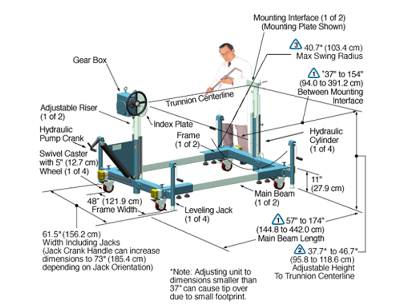
XD747DB-HYD
XD747DB-HYD Data Sheet
The Model XD747DB-HYD-J2-IND15-P8-B063 shown below is typical and representative of the XD747DB-HYD Models. For more information on specifying a holding fixture, see the 700 SERIES OPTIONS page and 700 SERIES CREATING A MODEL NUMBER pdf.
Product Features:
- Safety Factor: 3
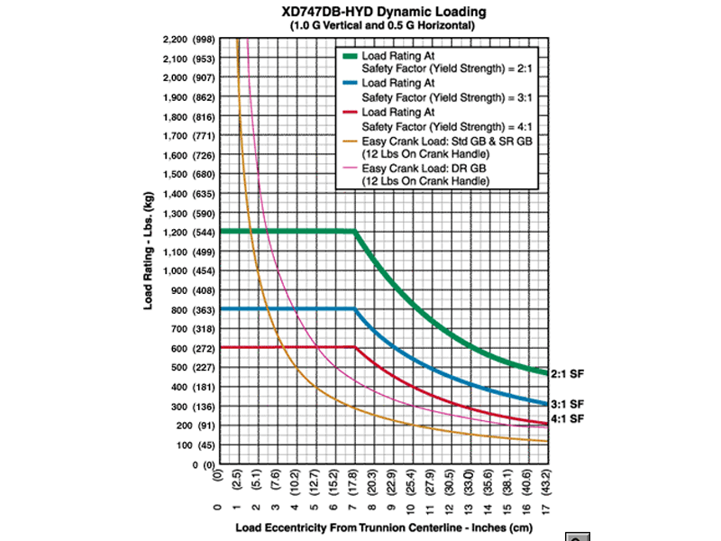
- Rated Load Capacity:
- Dynamic, 0″ eccentricity: 800 lbs. (363 kg.)
- Dynamic, 5″ eccentricity: 800 lbs. (363 kg.)
- Note: The hydraulic cylinders are single acting and a minimum load of 150 lbs is recommended to activate the return (compression) stroke and to give good synchronization of the risers.
- Operating Temperature: +32 to +104 °F (0 to +40 °C). Contact factory for special applications with extended operating temperatures.
- Choice of Trunnion Interface/Mount/Clamp Options:
- Angle Interface
- Mounting Plate Interface
- Synchronized Hydraulic Risers
The hydraulic risers can adjust the height of the part-to-be-handled while it is attached to the trunnion interfaces. Turning the pump crank clockwise or counter-clockwise causes the risers to raise or lower in unison. - Choice of Main Beam Length
- Main Beam Ball Lock Pin: Reliably prevents End Frames from slipping on Main Beam
- Gearbox: 60:1 ratio with 12″ diameter crank
- Casters: 5″ diameter x 2″ wide wheel with polyurethane tread, sealed swivel bearing and Tech-lock brake
- Materials: Steel construction
- Finish: Flotron Blue powder coat with selected parts zinc plated.
- A smaller than standard swing radius may be recommended for some applications. See the “Technical Section” under “Holding Fixture Safety” on page 3 of 7 concerning “Unexpected Accident Loads” and the chart on page 4 of 7 referring to “Maximum Recommended Swing Radius“.
- Optional Main Beam Lengths
- Optional Trunnion Interface/Mount/Clamp
- Optional Index Plate
- Optional Index Stops
- Optional Casters
- Optional Leveling Jacks
- Optional Gearboxes incorporating heavy duty, low backlash and stairstep resistant features
- Optional finishes for clean room compatibility
- Optional Ground Lug and Drag Chain for use in electrostatically protected areas (EPA’s)
- For more about 700 Series Options click here
As Flotron is constantly improving products and methods of manufacturing, we reserve the right to modify and/or change design or specifications without notice. Please contact Flotron for verification of critical dimensions and specifications.
For 700 Series – Creating a Model Number pdf click here.
For clarification of terms or phrases, please see the Holding Fixtures Definitions page.
XD739DB-HYD
XD739DB-HYD Data Sheet
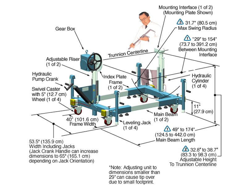
The Model XD739DB-HYD-J2-IND15-P8-B048 shown below is typical and representative of the XD739DB-HYD Models. For more information on specifying a holding fixture see the 700 SERIES OPTIONS page and 700 SERIES CREATING A MODEL NUMBER pdf.
Product Features:
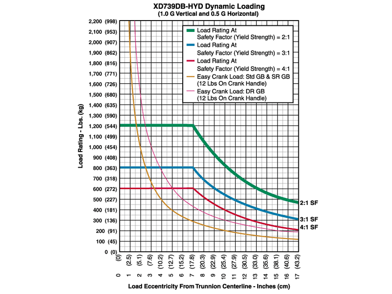
- Safety Factor: 3
- Rated Load Capacity:
- Dynamic, 0″ eccentricity: 800 lbs. (363 kg.)
- Dynamic, 5″ eccentricity: 800 lbs. (363 kg.)
- Note: The hydraulic cylinders are single acting and a minimum load of 150 lbs is recommended to activate the return (compression) stroke and to give good synchronization of the risers.
- Operating Temperature: +32 to +104 °F (0 to +40 °C). Contact factory for special applications with extended operating temperatures.
- Choice of Trunnion Interface/Mount/Clamp Options:
- Angle Interface
- Mounting Plate Interface
- Synchronized Hydraulic Risers
The hydraulic risers can adjust the height of the part-to-be-handled while it is attached to the trunnion interfaces. Turning the pump crank clockwise or counter-clockwise causes the risers to raise or lower in unison. - Choice of Main Beam Length
- Main Beam Ball Lock Pin: Reliably prevents End Frames from slipping on Main Beam
- Gearbox: 60:1 ratio with 12″ diameter crank
- Casters: 5″ diameter x 2″ wide wheel with polyurethane tread, sealed swivel bearing and Tech-lock brake
- Materials: Steel construction
- Finish: Flotron Blue powder coat with selected parts zinc plated.
- A smaller than standard swing radius may be recommended for some applications. See the “Technical Section” under “Holding Fixture Safety” on page 3 of 7 concerning “Unexpected Accident Loads” and the chart on page 4 of 7 referring to “Maximum Recommended Swing Radius“.
- Optional Main Beam Lengths
- Optional Trunnion Interface/Mount/Clamp
- Optional Index Plate
- Optional Index Stops
- Optional Casters
- Optional Leveling Jacks
- Optional Gearboxes incorporating heavy duty, low backlash and stairstep resistant features
- Optional finishes for clean room compatibility
- Optional Ground Lug and Drag Chain for use in electrostatically protected areas (EPA’s)
- For more about 700 Series Options click here
As Flotron is constantly improving products and methods of manufacturing, we reserve the right to modify and/or change design or specifications without notice. Please contact Flotron for verification of critical dimensions and specifications.
For 700 Series – Creating a Model Number pdf click here.
For clarification of terms or phrases, please see the Holding Fixtures Definitions page.
