Archives
961
961 Data Sheet
The Model 961-J2-IND15-P15/A36-B074 shown below is typical and representative of the 961 Models. For more information on specifying a holding fixture, see the 900 SERIES OPTIONS page and 900 SERIES CREATING A MODEL NUMBER pdf.
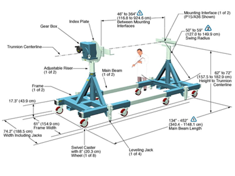
The maximum distance between mounting interfaces is directly related to the main beam length. Specify the distance between mounting interfaces to be at or slightly larger than the length of the part-to-be-handled. The fixture can be adjusted to accommodate smaller length parts, however, the main beam(s) extending from each end frame may be inconvenient. For more information see the 900 SERIES OPTIONS page and 900 SERIES CREATING A MODEL NUMBER pdf.
A smaller than standard swing radius may be recommended for some applications. See the “Technical Section” under “Holding Fixture Safety” on page 3 of 7 concerning “Unexpected Accident Loads” and the chart on page 4 of 7 referring to “Maximum Recommended Swing Radius”
Product Features:
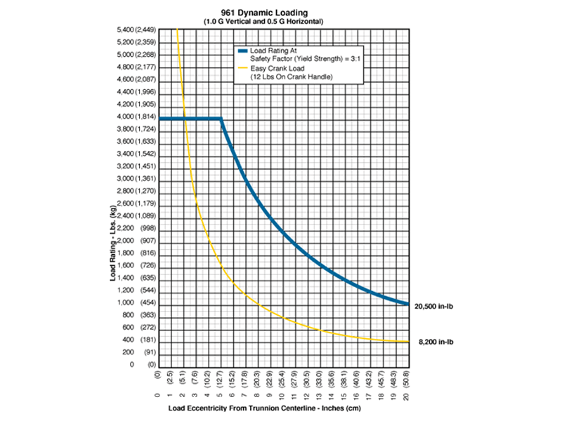
- Safety Factor: 3
- Rated Load Capacity:
- Dynamic, 0″ to 5.1″ eccentricity: 4,000 lbs. (1,814 kg.)
- Dynamic, 10″ eccentricity: 2,050 lbs. (930 kg.)
- Operating Temperature: +32 to +104 °F (0 to +40 °C). Contact factory for special applications with extended operating temperatures.
- Combination Mounting Plate / Angle Interface
- Choice of Main Beam Length
- Main Beam Ball Lock Pins: Reliably prevents End Frames from slipping on Main Beams
- Gearbox: Low backlash, non-backdriving stairstep resistant design with 250:1 ratio and 8″ diameter crank
- Self Aligning Couplings: These zero backlash couplings allow about ½ degree misalignment between load and fixture.
- Gearbox Hub: The zero backlash gearbox hub attaches the gearbox shaft to the index plate and mounting interface. The hub is designed to withstand both torque and overhung loads.
- Casters: 8″ diameter x 3″ wide wheel with polyurethane tread, kingpinless swivel bearing, Tread Lock brake and swivel lock
- Index Plate: Standard with 15° index plate and index stops
- Materials: Steel construction
- Finish: Flotron Blue powder coat with selected parts zinc plated.
- A smaller than standard swing radius may be recommended for some applications. See the “Technical Section” under “Holding Fixture Safety” on page 3 of 7 concerning “Unexpected Accident Loads” and the chart on page 4 of 7 referring to “Maximum Recommended Swing Radius“.
- Optional Ground Lug and Drag Chain for use in electrostatically protected areas (EPA’s)
- Optional Main Beam lengths
- Optional Leveling Jacks
- Optional finishes for clean room compatibility
- For more about 900 Series Options click here
All data presented is based on no modifications to the product.
As Flotron is constantly improving products and methods of manufacturing, we reserve the right to modify and/or change design or specifications without notice. Please contact Flotron for verification of critical dimensions and specifications.
For 900 Series – Creating a Model Number pdf click here.
For clarification of terms or phrases, please see the Holding Fixtures Definitions page.
CJ-6000
CJ-6000 Data Sheet
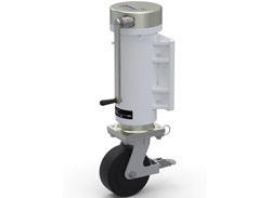
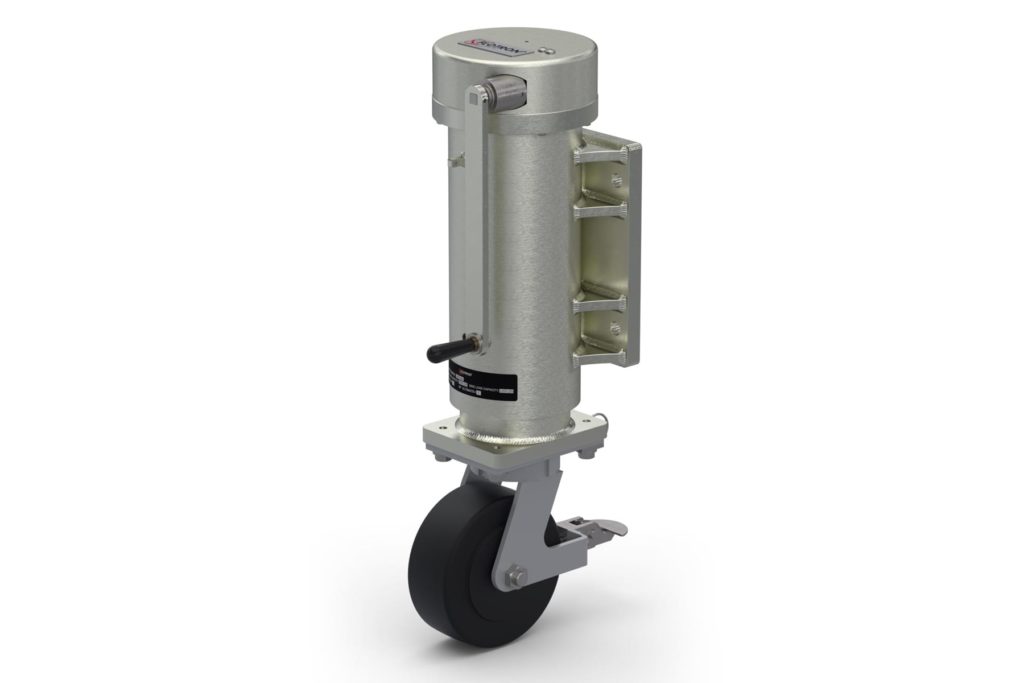
The Model CJ-6000 shown below is typical and representative of the CJ-6000 Models. For more information on specifying a jack, see the JACK OPTIONS page and JACK CREATING A MODEL NUMBER pdf..
Click on Caster Jack image for an Interactive experience
[dcb name=styling-click-for-experience-text]
Product Features:
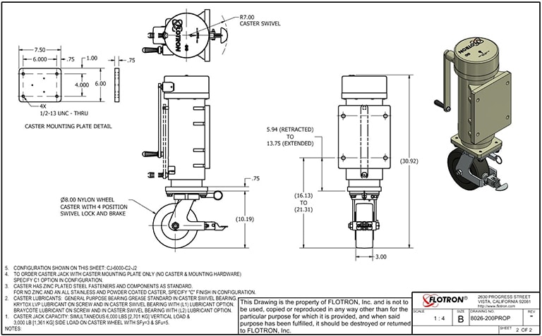
- Safety Factors: SFy=3 and SFu=5
- Rated Load Capacity: Simultaneous 6,000 lbs. (2,721 kg.) vertical load and 3,000 lb (1,361 kg.) side load in any direction.
- Operating Temperature: +32° to +104°F (0 to +40 °C). Contact Flotron for special applications with extended operating temperatures.
- Hand Crank: 12″ long removable crank to reveal a 1/2″ square drive input. When the handle is removed, the jack can be raised/lowered with a standard hand drill (300 rpm max non-impact)
- Input Clutch: Pre-set at Flotron to prevent damage to jack the at end the of travel.
- Turns per inch lift: 50 turns of handle per inch lift of jack.
- Materials: Steel and aluminum construction. Stainless steel fasteners. Bronze nut.
- Finish: Steel and Aluminum parts nickel plated. Caster body powder coated with zinc plated hardware. For additional caster finish options, click here
- Lubricants: Synco super lube grease standard on screw threads. General purpose bearing grease standard in caster swivel bearing. All other bearings or gears are either self-lubricating or sealed. For additional lubricant options, click here
All data presented is based on no modifications to the product.
As Flotron is constantly improving products and methods of manufacturing, we reserve the right to modify and/or change design or specifications without notice. Please contact Flotron for verification of critical dimensions and specifications.
For Jack – Creating a Model Number pdf click here.
For clarification of terms or phrases, please see the Holding Fixtures Definitions page.
872
872 Data Sheet
The Model 872-J5-IND15-P12/A30-B104 shown below is typical and representative of the 872 Models. For more information on specifying a holding fixture, see the 800 SERIES OPTIONS page and 800 SERIES CREATING A MODEL NUMBER pdf.
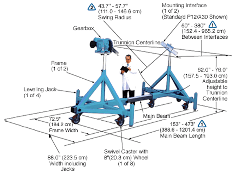
The maximum distance between mounting interfaces is directly related to the main beam length. Specify the distance between mounting interfaces to be at or slightly larger than the length of the part-to-be-handled. The fixture can be adjusted to accommodate smaller length parts, however, the main beam(s) extending from each end frame may be inconvenient. For more information see the 800 SERIES OPTIONS page and 800 SERIES CREATING A MODEL NUMBER pdf.
A smaller than standard swing radius may be recommended for some applications. See the “Technical Section” under “Holding Fixture Safety” on page 3 of 7 concerning “Unexpected Accident Loads” and the chart on page 4 of 7 referring to “Maximum Recommended Swing Radius”
Product Features:
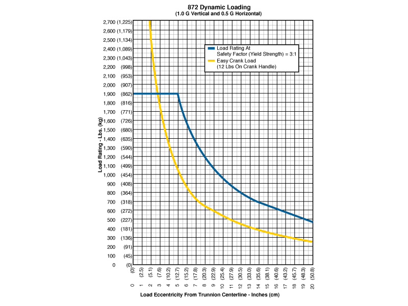
- Safety Factor: 3
- Rated Load Capacity:
- Dynamic, 0″ to 3.5″ eccentricity: 1,900 lbs. (862 kg.)
- Dynamic, 10″ eccentricity: 940 lbs. (426 kg.)
- Operating Temperature: +32 to +104 °F (0 to +40 °C). Contact factory for special applications with extended operating temperatures.
- Combination Mounting Plate / Angle Interface
- Choice of Main Beam Length
- Main Beam Ball Lock Pins: Reliably prevents End Frames from slipping on Main Beam
- Gearbox: Low backlash, non-backdriving stairstep resistant design with 250:1 ratio and 8″ diameter crank
- Self Aligning Couplings: These zero backlash couplings allow about ½ degree misalignment between load and fixture.
- Gearbox Hub: The zero backlash gearbox hub attaches the gearbox shaft to the index plate and mounting interface. The hub is designed to withstand both torque and overhung loads.
- Casters: 8″ diameter x 3″ wide wheel with polyurethane tread, kingpinless swivel bearing, Tread Lock brake and swivel lock
- Index Plate: Standard with 15° index plate and index stops
- Materials: Steel construction
- Finish: Flotron Blue powder coat with selected parts zinc plated.
- A smaller than standard swing radius may be recommended for some applications. See the “Technical Section” under “Holding Fixture Safety” on page 3 of 7 concerning “Unexpected Accident Loads” and the chart on page 4 of 7 referring to “Maximum Recommended Swing Radius“.
- Optional Ground Lug and Drag Chain for use in electrostatically protected areas (EPA’s)
- Optional Main Beam lengths
- Optional Leveling Jacks
- Optional finishes for clean room compatibility
- For more about 800 Series Options click here
All data presented is based on no modifications to the product.
As Flotron is constantly improving products and methods of manufacturing, we reserve the right to modify and/or change design or specifications without notice. Please contact Flotron for verification of critical dimensions and specifications.
For 800 Series – Creating a Model Number pdf click here.
860
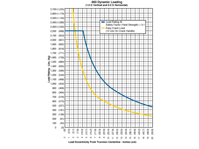
860 Data Sheet
The Model 860-J5-IND15-P12-B089 shown below is typical and representative of the 860 Models. For more information on specifying a holding fixture, see the 800 SERIES OPTIONS page and 800 SERIES CREATING A MODEL NUMBER pdf.
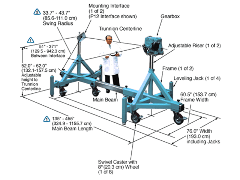
The maximum distance between mounting interfaces is directly related to the main beam length. Specify the distance between mounting interfaces to be at or slightly larger than the length of the part-to-be-handled. The fixture can be adjusted to accommodate smaller length parts, however, the main beam(s) extending from each end frame may be inconvenient. For more information see the 800 SERIES OPTIONS page and 800 SERIES CREATING A MODEL NUMBER pdf.
A smaller than standard swing radius may be recommended for some applications. See the “Technical Section” under “Holding Fixture Safety” on page 3 of 7 concerning “Unexpected Accident Loads” and the chart on page 4 of 7 referring to “Maximum Recommended Swing Radius”
Product Features:
- Safety Factor: 3
- Rated Load Capacity:
- Dynamic, 0″ to 4″ eccentricity: 2,200 lbs. (998 kg.)
- Dynamic, 10″ eccentricity: 940 lbs. (426 kg.)
- Operating Temperature: +32 to +104 °F (0 to +40 °C). Contact factory for special applications with extended operating temperatures.
- Combination Mounting Plate / Angle Interface
- Choice of Main Beam Length
- Main Beam Ball Lock Pins: Reliably prevents End Frames from slipping on Main Beam
- Gearbox: Low backlash, non-backdriving stairstep resistant design with 250:1 ratio and 8″ diameter crank
- Self Aligning Couplings: These zero backlash couplings allow about ½ degree misalignment between load and fixure.
- Gearbox Hub: The zero backlash gearbox hub attaches the gearbox shaft to the index plate and mounting interface. The hub is designed to withstand both torque and overhung loads.
- Casters: 8″ diameter x 3″ wide wheel with polyurethane tread, kingpinless swivel bearing, Tread Lock brake and swivel lock
- Index Plate: Standard with 15° index plate and index stops
- Materials: Steel construction
- Finish: Blue Paint or Powder Coat (at manufacturer’s discretion), with selected parts zinc plated. Other finishes available upon request
- Price Range: $38K – $64K
- A smaller than standard swing radius may be recommended for some applications. See the “Technical Section” under “Holding Fixture Safety” on page 3 of 7 concerning “Unexpected Accident Loads” and the chart on page 4 of 7 referring to “Maximum Recommended Swing Radius”
- Optional Ground Lug and Drag Chain for use in electrostatically protected areas (EPA’s)
- Optional Main Beam lengths
- Optional Leveling Jacks
- Optional finishes for clean room compatibility
- For more about 800 Series Options click here
All data presented is based on no modifications to the product.
As Flotron is constantly improving products and methods of manufacturing, we reserve the right to modify and/or change design or specifications without notice. Please contact Flotron for verification of critical dimensions and specifications.
For 800 Series – Creating a Model Number pdf click here.
For clarification of terms or phrases, please see the Holding Fixtures Definitions page.
CJ-3250
CJ-3250 Data Sheet
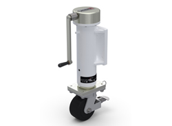
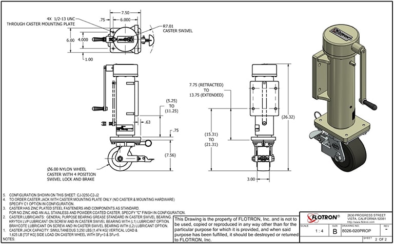
The Model CJ-3250 shown below is typical and representative of the CJ-3250 Models. For more information on specifying a jack, see the JACK OPTIONS page and JACK CREATING A MODEL NUMBER pdf.
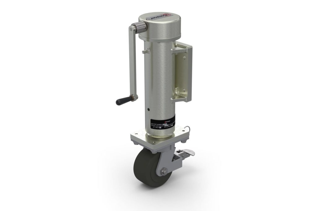
Click on Caster Jack image for an Interactive experience
[dcb name=styling-click-for-experience-text]
Product Features:
- Safety Factors: SFy=3 and SFu=5
- Rated Load Capacity: Simultaneous 3,250 lbs. (1,474 kg.) vertical load and 1,625 lb (737 kg.) side load in any direction.
- Operating Temperature: +32° to +104°F (0 to +40 °C). Contact Flotron for special applications with extended operating temperatures.
- Hand Crank: 10″ long removable crank to reveal a 3/8″ square drive input. When the handle is removed, the jack can be raised/lowered with a standard hand drill (300 rpm max non-impact)
- Input Clutch: Pre-set at Flotron to prevent damage to the jack at the end of travel.
- Turns per inch lift: 20 turns of handle per inch lift of jack.
- Materials: Steel and aluminum construction. Stainless steel fasteners. Bronze nut.
- Finish: Steel and Aluminum parts nickel plated. Caster body powder coated with zinc plated hardware. For additional caster finish options, click here
- Lubricants: Synco super lube grease standard on screw threads. General purpose bearing grease standard in caster swivel bearing. All other bearings or gears are either self-lubricating or sealed. For additional lubricant options, click here
All data presented is based on no modifications to the product.
As Flotron is constantly improving products and methods of manufacturing, we reserve the right to modify and/or change design or specifications without notice. Please contact Flotron for verification of critical dimensions and specifications.
For Jack – Creating a Model Number pdf click here.
For clarification of terms or phrases, please see the Holding Fixtures Definitions page.
848
848 Data Sheet
The Model 848-J5-IND15-P12/A30-B074 shown below is typical and representative of the 848 Models. For more information on specifying a holding fixture, see the 800 SERIES OPTIONS page and 800 SERIES CREATING A MODEL NUMBER pdf.
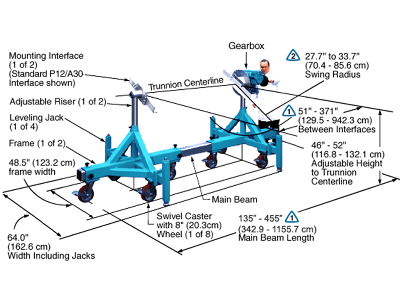
The maximum distance between mounting interfaces is directly related to the main beam length. Specify the distance between mounting interfaces to be at or slightly larger than the length of the part-to-be-handled. The fixture can be adjusted to accommodate smaller length parts, however, the main beam(s) extending from each end frame may be inconvenient. For more information see the 800 SERIES OPTIONS page and 800 SERIES CREATING A MODEL NUMBER pdf.
A smaller than standard swing radius may be recommended for some applications. See the “Technical Section” under “Holding Fixture Safety” on page 3 of 7 concerning “Unexpected Accident Loads” and the chart on page 4 of 7 referring to “Maximum Recommended Swing Radius”
Product Features:
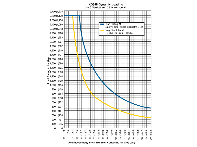
- Safety Factor: 3
- Rated Load Capacity:
- Dynamic, 0″ to 3.5″ eccentricity: 2,600 lbs. (1,179 kg.)
- Dynamic, 10″ eccentricity: 940 lbs. (426 kg.)
- Operating Temperature: +32 to +104 °F (0 to +40 °C). Contact factory for special applications with extended operating temperatures.
- Combination Mounting Plate / Angle Interface
- Choice of Main Beam Length
- Main Beam Ball Lock Pins: Reliably prevents End Frames from slipping on Main Beam
- Gearbox: Low backlash, non-backdriving stairstep resistant design with 250:1 ratio and 8″ diameter crank
- Self Aligning Couplings: These zero backlash couplings allow about ½ degree misalignment between load and fixture.
- Gearbox Hub: The zero backlash gearbox hub attaches the gearbox shaft to the index plate and mounting interface. The hub is designed to withstand both torque and overhung loads.
- Casters: 8″ diameter x 3″ wide wheel with polyurethane tread, kingpinless swivel bearing, Tread Lock brake and swivel lock
- Index Plate: Standard with 15° index plate and index stops
- Materials: Steel construction
- Finish: Flotron Blue powder coat with selected parts zinc plated.
- A smaller than standard swing radius may be recommended for some applications. See the “Technical Section” under “Holding Fixture Safety” on page 3 of 7 concerning “Unexpected Accident Loads” and the chart on page 4 of 7 referring to “Maximum Recommended Swing Radius“.
- Optional Ground Lug and Drag Chain for use in electrostatically protected areas (EPA’s)
- Optional Main Beam lengths
- Optional Leveling Jacks
- Optional finishes for clean room compatibility
- For more about 800 Series Options click here
All data presented is based on no modifications to the product.
As Flotron is constantly improving products and methods of manufacturing, we reserve the right to modify and/or change design or specifications without notice. Please contact Flotron for verification of critical dimensions and specifications.
For 800 Series – Creating a Model Number pdf click here.
For clarification of terms or phrases, please see the Holding Fixtures Definitions page.
CJ-2500
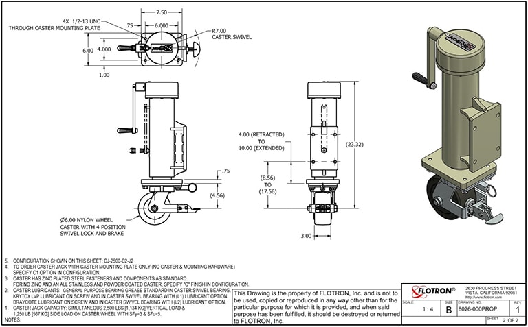
CJ-2500 Data Sheet
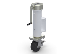
The Model CJ-2500 shown below is typical and representative of the CJ-2500 Models. For more information on specifying a jack, see the JACK OPTIONS page and JACK CREATING A MODEL NUMBER pdf.
Click on Caster Jack image for an Interactive experience
[dcb name=styling-click-for-experience-text]
Product Features:
- Safety Factors: SFy=3 and SFu=5
- Rated Load Capacity: Simultaneous 2,500 lbs. (1,134 kg.) vertical load and 1,250 lb (567 kg.) side load in any direction.
- Operating Temperature: +32° to +104°F (0 to +40 °C). Contact Flotron for special applications with extended operating temperatures.
- Hand Crank: 8″ long removable crank to reveal a 3/8″ square drive input. When the handle is removed, the jack can be raised/lowered with a standard hand drill (300 rpm max non-impact)
- Input Clutch: Pre-set at Flotron to prevent damage to the jack at the end of travel.
- Turns per inch lift: 20 turns of handle per inch lift of jack.
- Materials: Steel and aluminum construction. Stainless steel fasteners. Bronze nut.
- Finish: Steel and Aluminum parts nickel plated. Caster body powder coated with zinc plated hardware. For additional caster finish options, click here
- Lubricants: Synco super lube grease standard on screw threads. General purpose bearing grease standard in caster swivel bearing. All other bearings or gears are either self-lubricating or sealed. For additional lubricant options, click here
All data presented is based on no modifications to the product.
As Flotron is constantly improving products and methods of manufacturing, we reserve the right to modify and/or change design or specifications without notice. Please contact Flotron for verification of critical dimensions and specifications.
For Jack – Creating a Model Number pdf click here.
For clarification of terms or phrases, please see the Holding Fixtures Definitions page.
XD759DB-HYD
XD759DB-HYD Data Sheet
The Model XD759DB-HYD-J2-IND15-P8-B078 shown below is typical and representative of the XD759DB-HYD Models. For more information on specifying a holding fixture, see the 700 SERIES OPTIONS page and 700 SERIES CREATING A MODEL NUMBER pdf.

The maximum distance between mounting interfaces is directly related to the main beam length. Specify the distance between mounting interfaces to be at or slightly larger than the length of the part-to-be-handled. The fixture can be adjusted to accommodate smaller length parts, however, the main beam(s) extending from each end frame may be inconvenient. For more information see the 700 SERIES OPTIONS page and 700 SERIES CREATING A MODEL NUMBER pdf.
Addition of the optional SR or DR gearbox decreases the vertical riser adjustment from 11.8″ to 9.8″ and increases the minimum trunnion height from 46.9″ to 48.9″.
A smaller than standard swing radius may be recommended for some applications. See the “Technical Section” under “Holding Fixture Safety” on page 3 of 7 concerning “Unexpected Accident Loads” and the chart on page 4 of 7 referring to “Maximum Recommended Swing Radius”
Product Features:
- Safety Factor: 3
- Rated Load Capacity:
- Dynamic, 0″ eccentricity: 800 lbs. (363 kg.)
- Dynamic, 5″ eccentricity: 800 lbs. (363 kg.)
- Note: The hydraulic cylinders are single acting and a minimum load of 150 lbs is recommended to activate the return (compression) stroke and to give good synchronization of the risers.
- Operating Temperature: +32 to +104 °F (0 to +40 °C). Contact factory for special applications with extended operating temperatures.
- Choice of Trunnion Interface/Mount/Clamp Options:
- Angle Interface
- Mounting Plate Interface
- Synchronized Hydraulic Risers
The hydraulic risers can adjust the height of the part-to-be-handled while it is attached to the trunnion interfaces. Turning the pump crank clockwise or counter-clockwise causes the risers to raise or lower in unison. - Choice of Main Beam Length
- Main Beam Ball Lock Pin: Reliably prevents End Frames from slipping on Main Beam
- Gearbox: 60:1 ratio with 12″ diameter crank
- Casters: 5″ diameter x 2″ wide wheel with polyurethane tread, sealed swivel bearing and Tech-lock brake
- Materials: Steel construction
- Finish: Blue Paint or Powder Coat (at manufacturer’s discretion), with selected parts zinc plated. Other finishes available upon request
- Trunnion Brake Knob
- Price Range: $15K – $33K
- A smaller than standard swing radius may be recommended for some applications. See the “Technical Section” under “Holding Fixture Safety” on page 3 of 7 concerning “Unexpected Accident Loads” and the chart on page 4 of 7 referring to “Maximum Recommended Swing Radius”
- Optional Main Beam Lengths
- Optional Trunnion Interface/Mount/Clamp
- Optional Index Plate
- Optional Index Stops
- Optional Casters
- Optional Leveling Jacks
- Optional Gearboxes incorporating heavy duty, low backlash and stairstep resistant features
- Optional finishes for clean room compatibility
- Optional Ground Lug and Drag Chain for use in electrostatically protected areas (EPA’s)
- For more about 700 Series Options click here
All data presented is based on no modifications to the product.
As Flotron is constantly improving products and methods of manufacturing, we reserve the right to modify and/or change design or specifications without notice. Please contact Flotron for verification of critical dimensions and specifications.
For 700 Series – Creating a Model Number pdf click here.
XD747DB-HYD
XD747DB-HYD Data Sheet
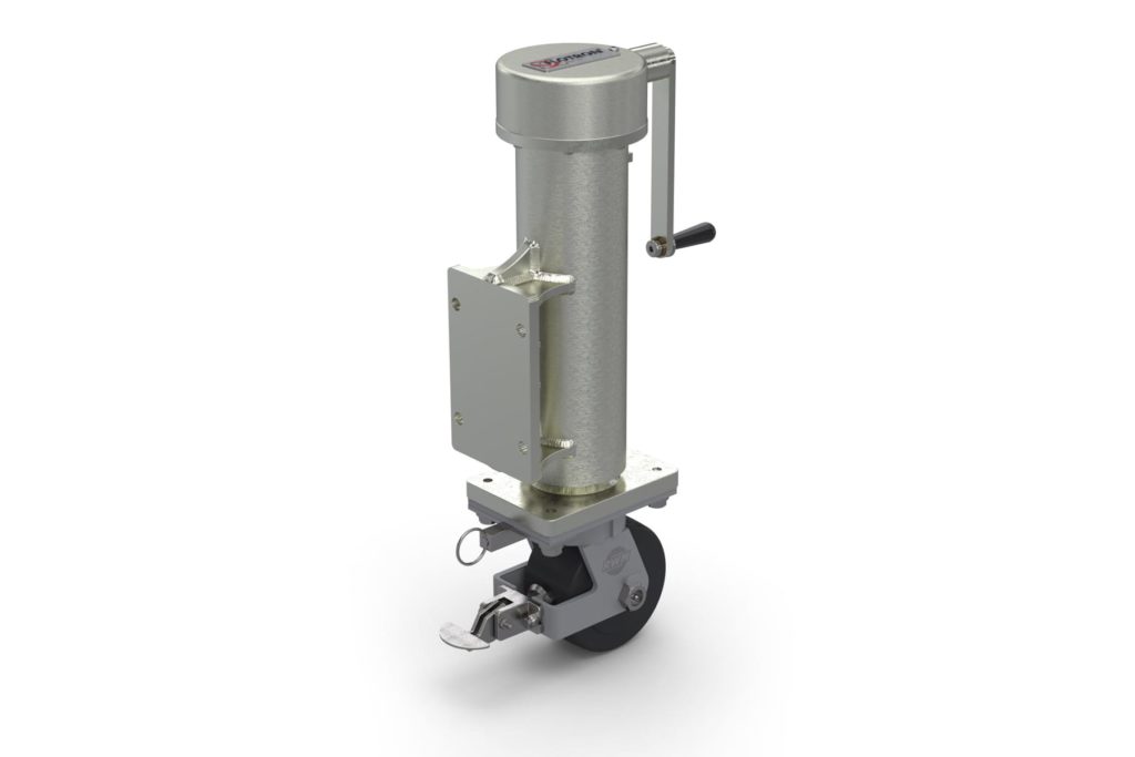
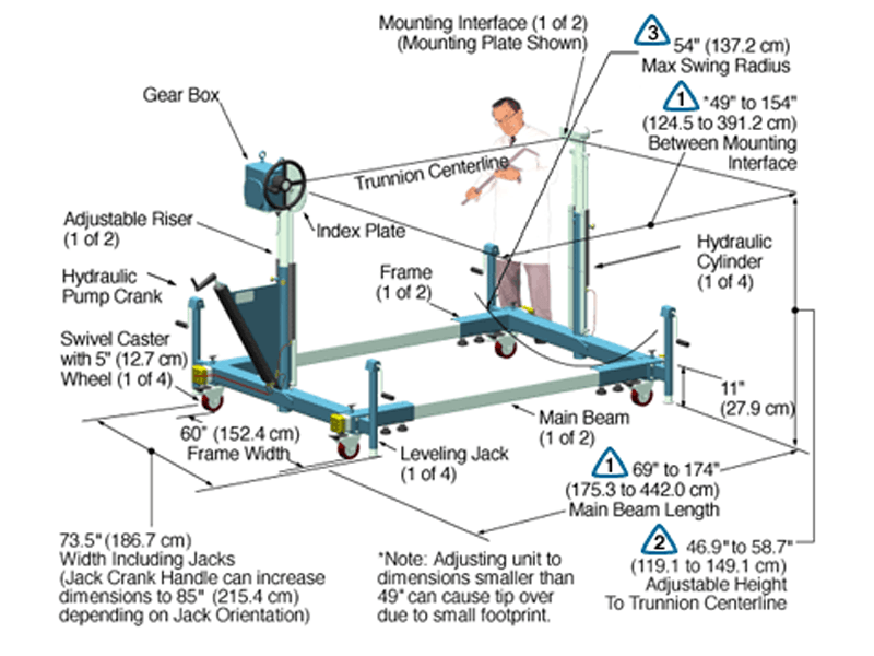
The Model XD747DB-HYD-J2-IND15-P8-B063 shown below is typical and representative of the XD747DB-HYD Models. For more information on specifying a holding fixture, see the 700 SERIES OPTIONS page and 700 SERIES CREATING A MODEL NUMBER pdf.
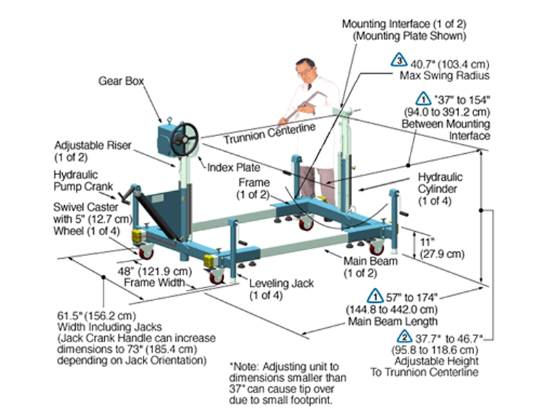
The maximum distance between mounting interfaces is directly related to the main beam length. Specify the distance between mounting interfaces to be at or slightly larger than the length of the part-to-be-handled. The fixture can be adjusted to accommodate smaller length parts, however, the main beam(s) extending from each end frame may be inconvenient. For more information see the 700 SERIES OPTIONS page and 700 SERIES CREATING A MODEL NUMBER pdf.
Addition of the optional SR or DR gearbox decreases the vertical riser adjustment from 12″ to 10″ and increases the minimum trunnion height from 46.7″ to 48.7″.
A smaller than standard swing radius may be recommended for some applications. See the “Technical Section” under “Holding Fixture Safety” on page 3 of 7 concerning “Unexpected Accident Loads” and the chart on page 4 of 7 referring to “Maximum Recommended Swing Radius”
Product Features:
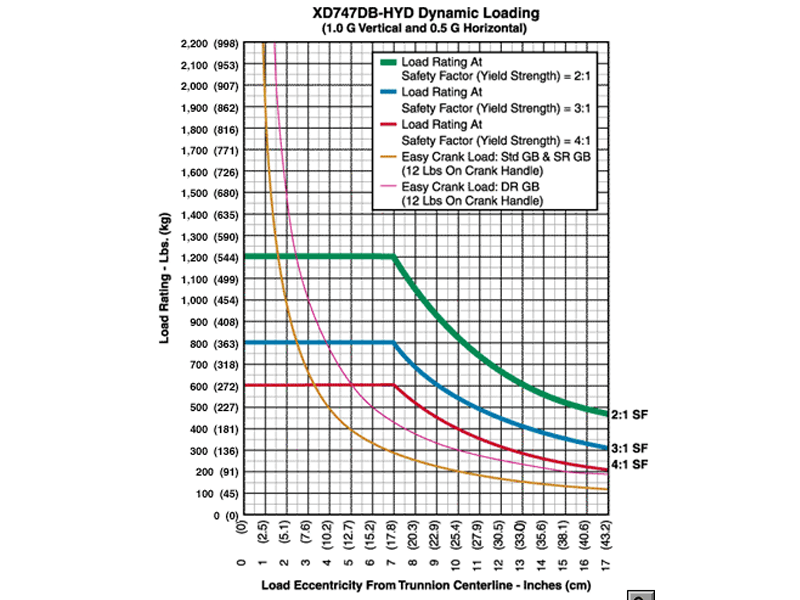
- Safety Factor: 3
- Rated Load Capacity:
- Dynamic, 0″ eccentricity: 800 lbs. (363 kg.)
- Dynamic, 5″ eccentricity: 800 lbs. (363 kg.)
- Note: The hydraulic cylinders are single acting and a minimum load of 150 lbs is recommended to activate the return (compression) stroke and to give good synchronization of the risers.
- Operating Temperature: +32 to +104 °F (0 to +40 °C). Contact factory for special applications with extended operating temperatures.
- Choice of Trunnion Interface/Mount/Clamp Options:
- Angle Interface
- Mounting Plate Interface
- Synchronized Hydraulic Risers
The hydraulic risers can adjust the height of the part-to-be-handled while it is attached to the trunnion interfaces. Turning the pump crank clockwise or counter-clockwise causes the risers to raise or lower in unison. - Choice of Main Beam Length
- Main Beam Ball Lock Pin: Reliably prevents End Frames from slipping on Main Beam
- Gearbox: 60:1 ratio with 12″ diameter crank
- Casters: 5″ diameter x 2″ wide wheel with polyurethane tread, sealed swivel bearing and Tech-lock brake
- Materials: Steel construction
- Finish: Flotron Blue powder coat with selected parts zinc plated.
- A smaller than standard swing radius may be recommended for some applications. See the “Technical Section” under “Holding Fixture Safety” on page 3 of 7 concerning “Unexpected Accident Loads” and the chart on page 4 of 7 referring to “Maximum Recommended Swing Radius“.
- Optional Main Beam Lengths
- Optional Trunnion Interface/Mount/Clamp
- Optional Index Plate
- Optional Index Stops
- Optional Casters
- Optional Leveling Jacks
- Optional Gearboxes incorporating heavy duty, low backlash and stairstep resistant features
- Optional finishes for clean room compatibility
- Optional Ground Lug and Drag Chain for use in electrostatically protected areas (EPA’s)
- For more about 700 Series Options click here
All data presented is based on no modifications to the product.
As Flotron is constantly improving products and methods of manufacturing, we reserve the right to modify and/or change design or specifications without notice. Please contact Flotron for verification of critical dimensions and specifications.
For 700 Series – Creating a Model Number pdf click here.
For clarification of terms or phrases, please see the Holding Fixtures Definitions page.